Flow rate measuring device

a flow rate and measuring device technology, applied in the direction of instruments, electric control, combustion air/fuel air treatment, etc., can solve the problems of rate measuring device b>1/b> producing detection error to fail to optimize the control of air-fuel ratio, and swirling stream to provide more complicated streams. , to achieve the effect of stably introducing, better accuracy and better accuracy

Inactive Publication Date: 2005-03-29
MITSUBISHI ELECTRIC CORP
View PDF21 Cites 70 Cited by
  • Summary
  • Abstract
  • Description
  • Claims
  • Application Information

AI Technical Summary

Benefits of technology

In accordance with the seventeenth aspect, a swirling stream that is directed to the introduction port arrives at the introduction port after having divided into a plurality of vortexes by the projections, and the divided vortexes are introduced into the measuring duct after having had the rotation weakened. Thus, flow rate measurement can be carried out with better accuracy.
In accordance with the eighteenth aspect, a swirling vortex can be ensured to be divided to carry out flow rate measurement with better accuracy.
In accordance with the nineteenth aspect, the fluid can be stably introduced at a greater amount to carry out flow rate measurement with better accuracy.
In accordance with the twentieth aspect, mounting of the flow rate measuring device to a plug-in type introduction system can be simplified to save a space required for an engine room and make an automobile assembling l

Problems solved by technology

In addition, swirling streams increase to provide more complicated streams for the following reasons.
As a result, the flow rate that is detected at the flow rate detecting element 31 changes, creating a problem to produce an error in flow rate detection.
When the air cleaner 2 that has changed with the lapse of time is used, the flow rate measuring device 1 produces an error in detection to fail optimized control of an air-fuel ratio.
As a result, the purifying function in an exhaust emission control system, such as a three-way catalyst, is adversely affected to introduce serious air pollution.
The emission regulation has been determined to be severer throughout the world for the twenty-first century, and an issue of a change in the introduction system with the lapse of time is predicted to become a big issue more and more.
In addition, a change in the introduction system with the lapse of time, variations in the assemblage of the air filter 3 or the air cleaner 2 change the flow velocity distribution in the air flow to create a problem in that an error in flow rate detection is produced.
However, the provision of the bell-mouthed cylindrical duct introduces a disadvantage in that the formation of a swirling stream is not taken into account though a decreasing effect to a non-uniform flow distribution or a disturbing degree is taken account to some extent.
When the revolution increases, a fluid in the measuring duct 140 has a distribution deviated toward outside by a centrifugal force to create a disadvantage in that a significant error in flow detection is produced at the flow rate detecting element 31 provided in the vicinity of the center of the measuring duct.
However, dense mounting of parts into an engine room is difficult to ensure a sufficient space for a pipe with the rectifying portion, and the demand for a plug-in type flow rate measuring device, which can be simply provided in an opening formed in the induction pipe 20, has become gradually greater in recent years.
Since such a plug-in type flow rate measuring device has no rectifying function therein, there has been created a disadvantage in that a rectifying grid 142 is required to be provided in an introduction passage in addition to the flow rate measuring device.
However, the arrangement has created a disadvantage in that the presence of a bent portion, where the flow is in

Method used


Image

  • Flow rate measuring device
  • Flow rate measuring device
  • Flow rate measuring device

Examples


embodiment 1

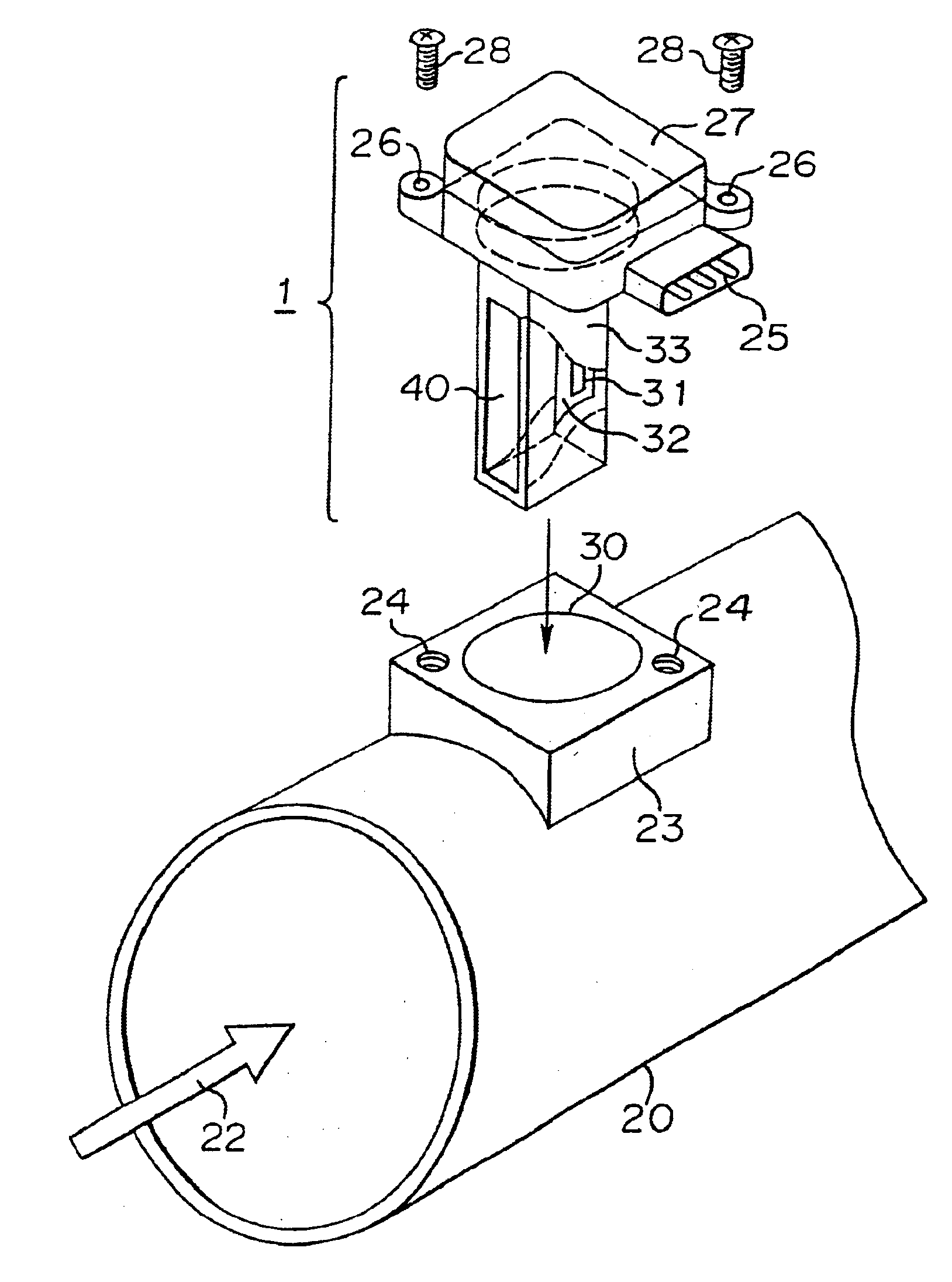
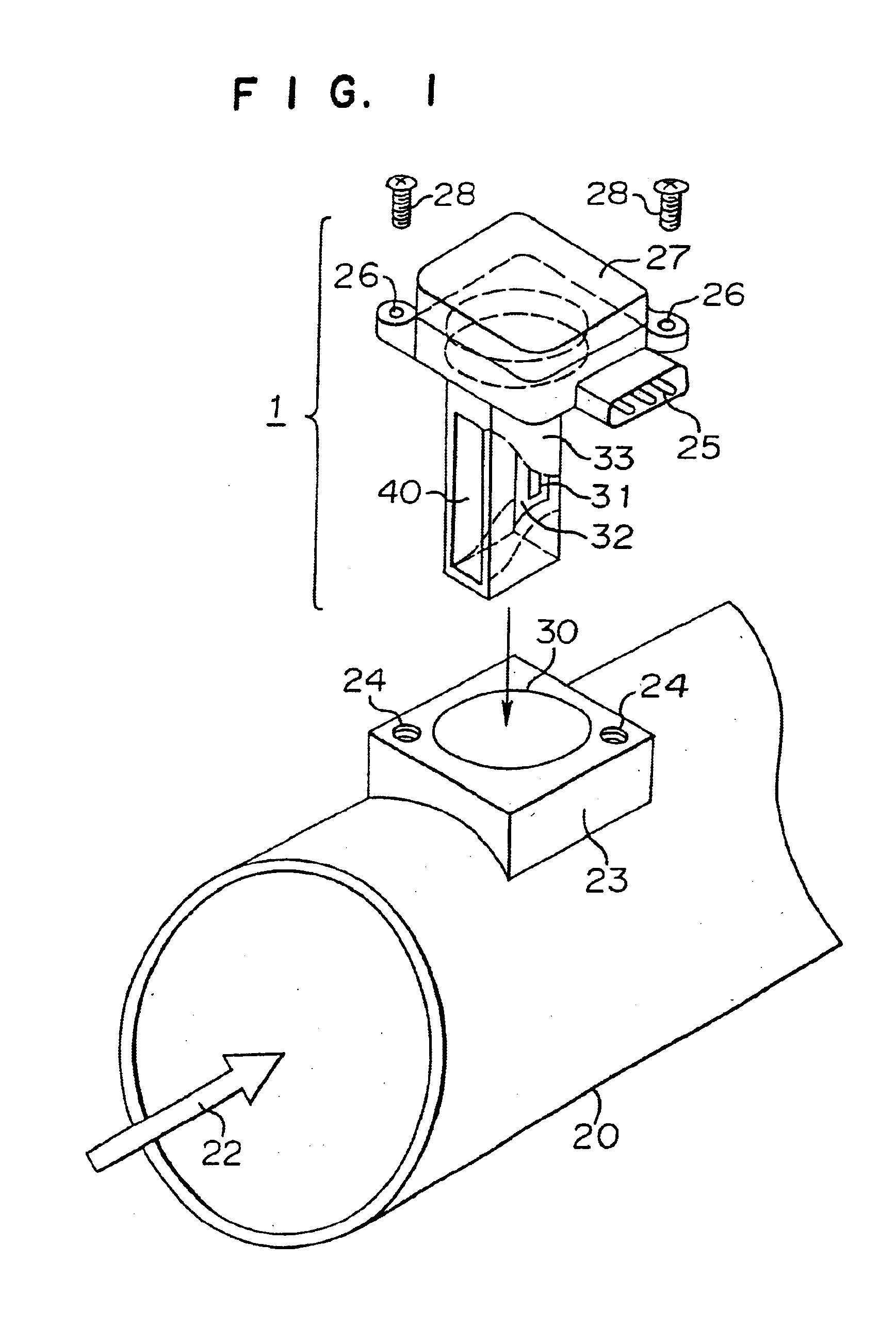
In FIG. 1 is shown a perspective view of the flow rate measuring device according to a first embodiment of the present invention. In this FIG., reference numeral 1 designates the flow rate measuring device, reference numeral 20 designates an induction pipe, reference numeral 22 designates an arrow to indicate the forward direction of intake air, reference numeral 23 designates a seat to mount the flow rate measuring device 1 to the induction pipe 20 by insertion, reference numerals 24 and 26 designate threaded holes to fixedly mount the flow rate measuring device 1 to the seat 23, reference numeral 28 designates bolts, reference numeral 25 designates a terminal for connection of signal lines, reference numeral 27 designates a cover for covering an electronic circuit board (not shown) arranged therein, reference numeral 30 designates an opening formed in the seat 23 and in a side wall of the induction pipe 20 for inserting the flow rate measuring device 1 into the induction pipe 20, ...

embodiment 2

In FIG. 20 is shown a front view of the flow rate measuring device according to a second embodiment of the present invention. In this FIG., reference numeral 46 designates one of opposite tapered walls. In this embodiment, the measuring duct 40 has the length in the transverse direction of the elongated introduction port or short sides gradually shortened toward the downstream direction between the introduction port 41 and the exit port 42 as in the length of the introduction port in the longitudinal direction. In other words, the transverse cross-sectional shape of the measuring duct 40 perpendicular to the flow is gradually shortened toward the downstream direction in terms of the length in the transverse direction as well in comparison with the mode of the first embodiment shown in FIG. 6(b).

Now, the operation will be explained. The explanation will be made, comparing this embodiment with the first embodiment for easy comprehension of the operation. In FIG. 21 is shown a schemati...

embodiment 3

A third embodiment provides an arrangement to stabilize streams in the measuring duct and further reduce an error in flow rate detection in a constant flow and a pulsating flow. In FIG. 23 is shown a perspective view of the flow rate measuring device according to the third embodiment. In this FIG., reference numeral 56 designates notches, which are formed in side walls of the post 33 at the downstream end of the measuring duct.

Now, this embodiment will be explained in comparison with the absence of the notches.56 for easy comprehension of the operation in the provision of the notches 56. In FIG. 24 is shown a schematic view to explain how streams flow in the provision of the notches. In FIG. 25 is shown a schematic view to explain how streams flow in the absence of the notches. In both FIGS., the post is shown to be cut in the transverse direction along the flow direction.

When the notches 56 are not provided, that is to say, when streams 34 and 36 join at the tails of two flat plate...


PUM


Abstract

A post in a fluid passage for passing a fluid flow extends across a part of the fluid flow; a measuring duct in the post extends through the post; and a flow rate detector is located in the measuring duct. The measuring duct has a fluid introduction port with an elongated shape, the measuring duct is constricted and has at least a portion located between the fluid introduction port and the flow rate detector, substantially smoothly narrowing toward a downstream direction of the flow in a longitudinal direction of the elongated shape.

Description

BACKGROUND OF THE INVENTION1. FIELD OF THE INVENTIONThe present invention relates to a flow rate measuring device, in particular a device for measuring the mass flow rate of intake air into an internal combustion engine.2. DISCUSSION OF BACKGROUNDBefore explaining prior art, a typical problem in the induction system for automobile engines will be explained. In FIG. 36 is shown a schematic cross-sectional view of the structure of an induction system for a typical automobile engine. In this FIG., reference numeral 1 designates an intake air flow rate measuring device for measuring the flow rate of intake air, and the reference numeral 31 designates a sensor in the device, or a flow rate detecting element. Reference numeral 2 designates an air cleaner, reference numeral 3 designates an air filter, reference numeral 4 designates arrows to indicate the flow direction of the intake air from the atmosphere, reference numeral 5 designates dirt and dust mingling in the air as contaminants, r...

Claims


Application Information

Patent Timeline
IPC IPC(8): F02D41/18F02M35/02F02M35/04G01F1/68F02D35/00G01F1/684G01F1/69G01F5/00
CPCF02D41/185F02D41/187G01F5/00G01F1/6842F02M35/021G01F1/68
Inventor HAMADA, SHINGOYONEZAWA, FUMIYOSHIURAMACHI, HIROYUKIYAMAKAWA, TOMOYAOSHIMA, TAKEHARUKOTOH, SATORU
Owner MITSUBISHI ELECTRIC CORP
Why Eureka
Try Eureka