Ferroelectric memory device

a ferroelectric memory and capacitor technology, applied in the direction of capacitors, solid-state devices, transistors, etc., can solve the problems of deterioration of the reliability of the ferroelectric memory device, and achieve the effect of eliminating the deterioration of the characteristics of the ferroelectric capacitor and improving reliability

Inactive Publication Date: 2005-03-29
PANASONIC CORP
View PDF8 Cites 6 Cited by
  • Summary
  • Abstract
  • Description
  • Claims
  • Application Information

AI Technical Summary

Benefits of technology

An object of the present invention is providing a ferroelectric memory device with improved reliability, in which the deterioration in characteristics of a ferroelectric capacitor can be eliminated by controlling an overlap area between a storage line and an underlying top electrode in a planar layout.
In this structure, a stress applied by the first interconnection layer to the ferroelectric capacitor or a leakage current flowing between adjacent portions of the first interconnection layer decreases, thus preventing decrease in early yield resulting from leakage failure and deterioration in retention characteristics. As a result, the reliability of the ferroelectric memory device can be improved.
In these embodiments, it is possible to prevent the characteristics of the ferroelectric capacitor from being deteriorated due to annealing conducted before the second interconnection layer is formed. In addition, the stress applied to the ferroelectric capacitor during the formation of the second interconnection layer can be relaxed.

Problems solved by technology

The reliability of this ferroelectric memory device sometimes deteriorates due to the infant mortality failure of the ferroelectric capacitor or degradation in retention characteristics thereof.

Method used


Image

  • Ferroelectric memory device
  • Ferroelectric memory device
  • Ferroelectric memory device

Examples


embodiment 1

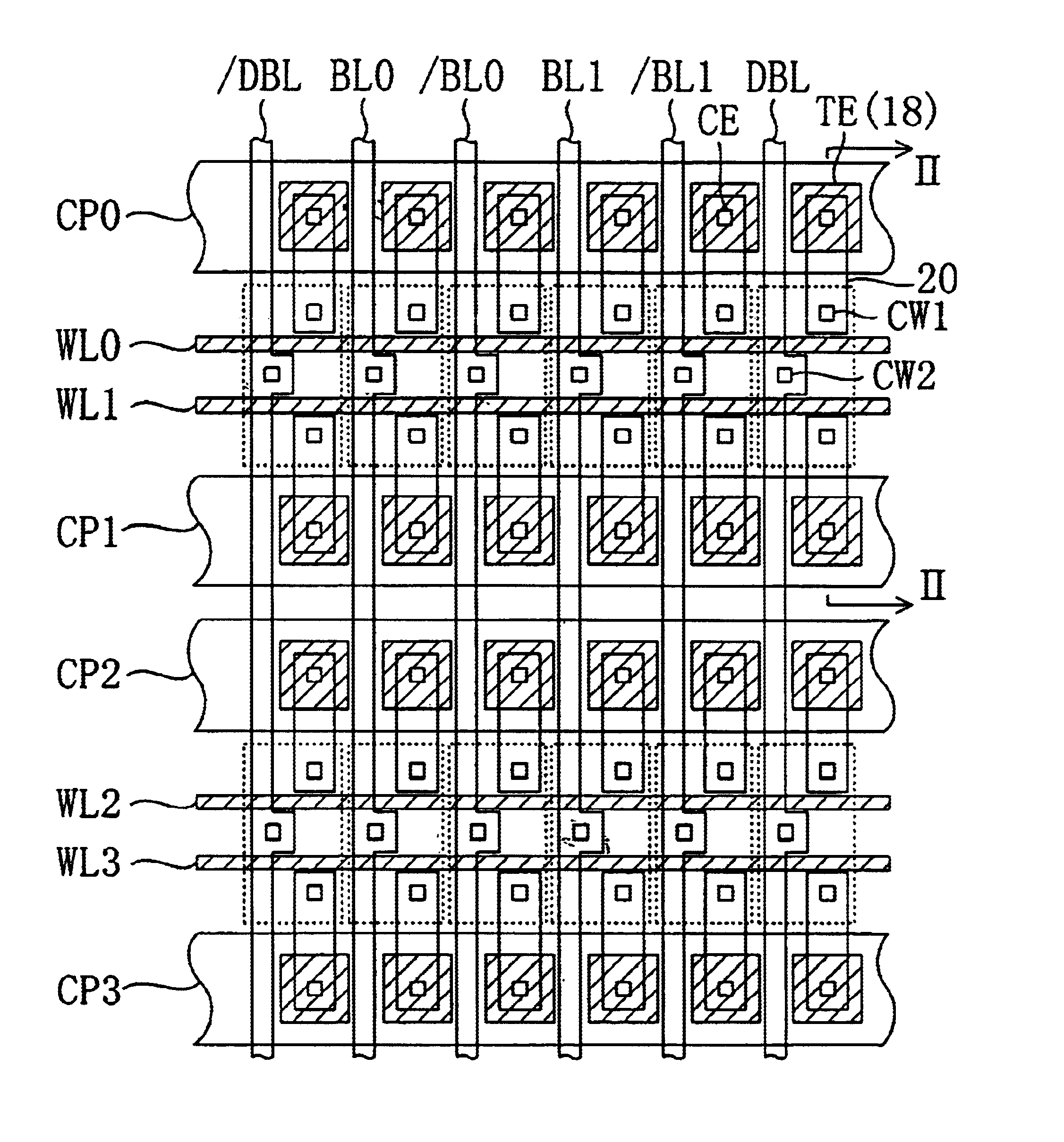
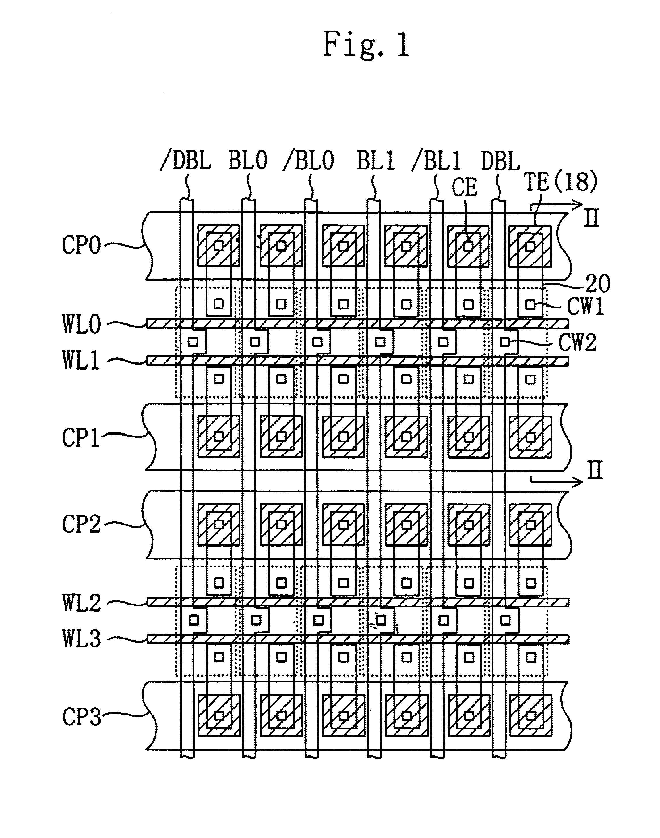
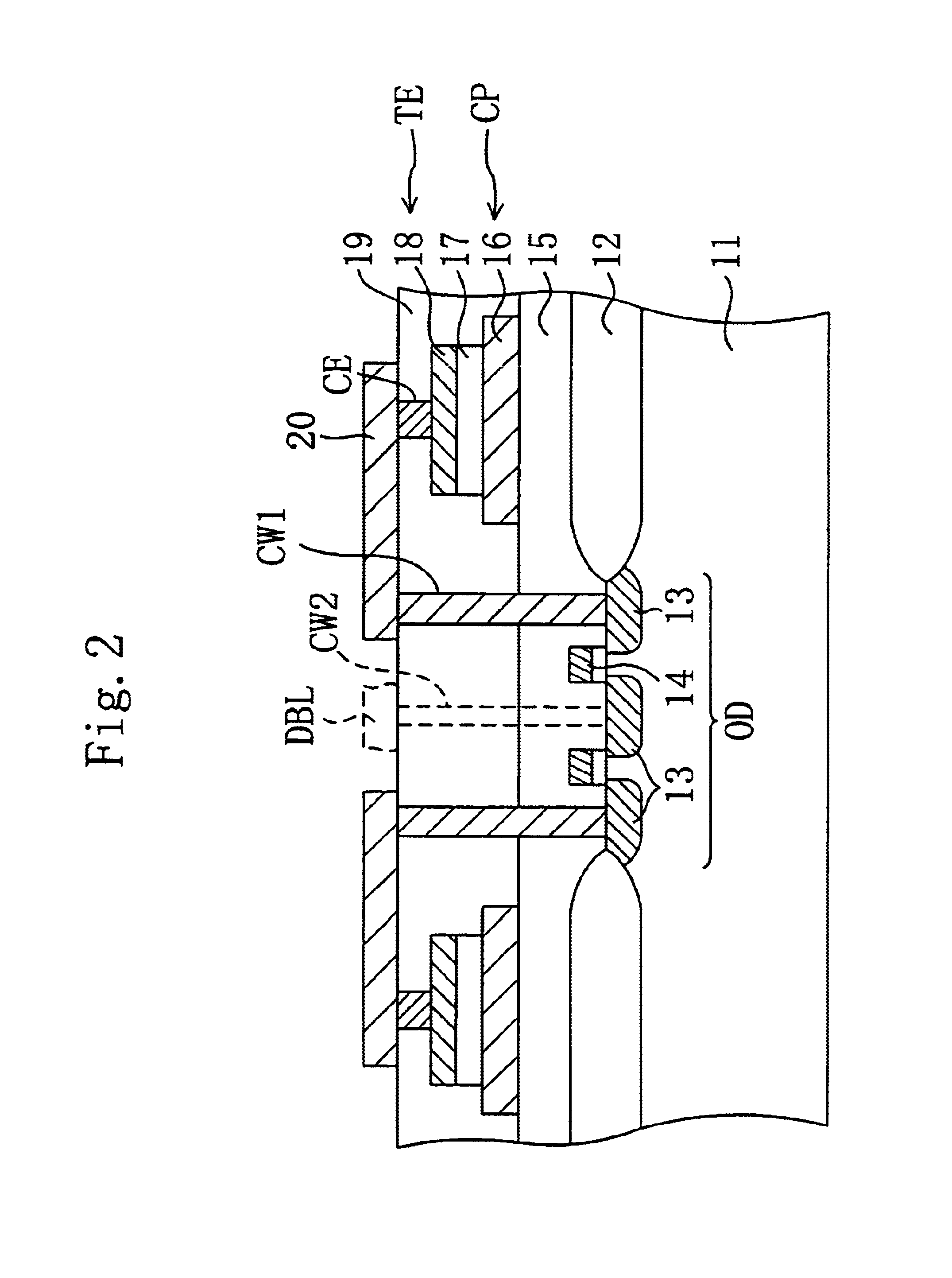
FIG. 1 is a plan view of an array of memory cells in a ferroelectric memory device according to a first embodiment of the present invention as viewed from above a layer in which bit lines are formed. FIG. 2 is a vertical cross-sectional view of the device taken along the line II—II in FIG. 1.

As shown in FIG. 2, an active region OD is formed to be surrounded by a LOCOS film 12 on an Si substrate 11. Within this active region OD, source / drain doped layers 13 and polysilicon gates 14 are provided. A first interlevel dielectric film 15 is formed over the Si substrate 11. Memory cell capacitors are formed at respective regions over the LOCOS film 12 on the first interlevel dielectric film 15. Each of these memory cell capacitors includes: a bottom electrode 16 made of a metal such as platinum or iridium; a ferroelectric film 17 made of a ferroelectric material described later; and a top electrode 18 also made of a metal such as platinum or iridium. A second interlevel dielectric film 19 ...

embodiment 2

FIG. 3 is a plan view of an array of memory cells according to a second embodiment of the present invention as viewed from above its layer in which bit lines are formed.

The ferroelectric memory device of the second embodiment is characterized in that the overlap area between each storage line 20 and an associated top electrode 18 (TE) is even smaller than that in the first embodiment. Specifically, as shown in FIG. 3, each storage line 20 has such a planar shape that the line width of the central region thereof is smaller than that of the other regions thereof. The line width of the central region is defined at the minimum value according to a design rule for forming the storage line. In the other respects, the structure of the second embodiment is the same as that of the first embodiment.

In the ferroelectric memory device of the second embodiment, the overlap area between each storage line 20 and an associated top electrode 18 is further reduced as compared to the ferroelectric mem...


PUM


Abstract

A memory cell transistor using a word line WL as the gate thereof is provided in an active region OD, and a ferroelectric capacitor, including bottom electrode, ferroelectric film and top electrode TE, is formed on a field oxide film. A first interconnection layer is made up of storage lines, each connecting the top electrode TE to one of doped layers of the memory cell transistor, and bit lines, each of which is connected to the other doped layer. In a planar layout, the storage line-intersects only one side of the top electrode TE and the bit line BL does not overlap with the top electrode TE. Thus, it is possible to prevent the retention characteristics of the ferroelectric capacitor from being deteriorated due to the stress applied by the first interconnection layer to the ferroelectric capacitor. As a result, the reliability of a ferroelectric memory device, including, in a memory cell, a ferroelectric capacitor with a ferroelectric film interposed between the bottom and top electrodes, can be improved.

Description

BACKGROUND OF THE INVENTIONThe present invention relates to a ferroelectric memory device, and more particularly relates to measures taken to improve the reliability thereof.Over the past few years, portable communications terminals, IC cards and the like have been rapidly popularized around the world. To operate these types of electronic units more efficiently, nonvolatile semiconductor memory devices for use in these units are increasingly required to operate at an even lower voltage and at an even higher speed while consuming even lower power. A ferroelectric memory device is one of strong candidate nonvolatile memory devices that are expected to fulfill these requirements at the same time. A device of this type includes a ferroelectric capacitor, in which a ferroelectric film is sandwiched between a pair of electrodes. Data can be stored thereon in a nonvolatile manner depending on whether the ferroelectric material within the capacitor is polarized in one direction or the other...

Claims


Application Information

Patent Timeline
Patent Type & Authority Patents(United States)
IPC IPC(8): H01L27/115H01L21/02H01L27/10H01L21/8242H01L21/8246H01L27/105H01L27/108
CPCH01L27/11502H01L28/55H10B53/00
Inventor HIRANO, HIROSHIGEHONDA, TOSHIYUKI
Owner PANASONIC CORP
Why Eureka
Try Eureka