Hot pluggable optical transceiver in a small form pluggable package

a technology of pluggable optical transceivers and pluggable packages, applied in the direction of optical elements, circuit optical details, instruments, etc., can solve the problems of increasing manufacturing costs, short interruptions in fiber optic devices, and inability to tolerate high temperatures during wave soldering

Inactive Publication Date: 2005-03-29
JDS UNIPHASE CORP
View PDF115 Cites 80 Cited by
  • Summary
  • Abstract
  • Description
  • Claims
  • Application Information

AI Technical Summary

Benefits of technology

The electrical element is implemented with vertically stacked receiver and transmitter printed circuit boards. The use of separate vertically stacked printed circuit boards allows packaging the functions of a GBIC w

Problems solved by technology

Because many of the optical elements of fiber optic modules use plastic materials, the optical elements can not tolerate the high temperatures experienced during wave soldering.
The additional step ther

Method used


Image

  • Hot pluggable optical transceiver in a small form pluggable package
  • Hot pluggable optical transceiver in a small form pluggable package
  • Hot pluggable optical transceiver in a small form pluggable package

Examples


Embodiment Construction

In the following detailed description of the present invention, numerous specific details are set forth in order to provide a thorough understanding of the present invention. However, it will be obvious to one skilled in the art that the present invention may be practiced without these specific details. In other instances well known methods, procedures, components, and circuits have not been described in detail so as not to unnecessarily obscure aspects of the present invention.

The present invention includes a method, apparatus and system for hot pluggable optical transceiver in a small form pluggable GBIC, LC type package.

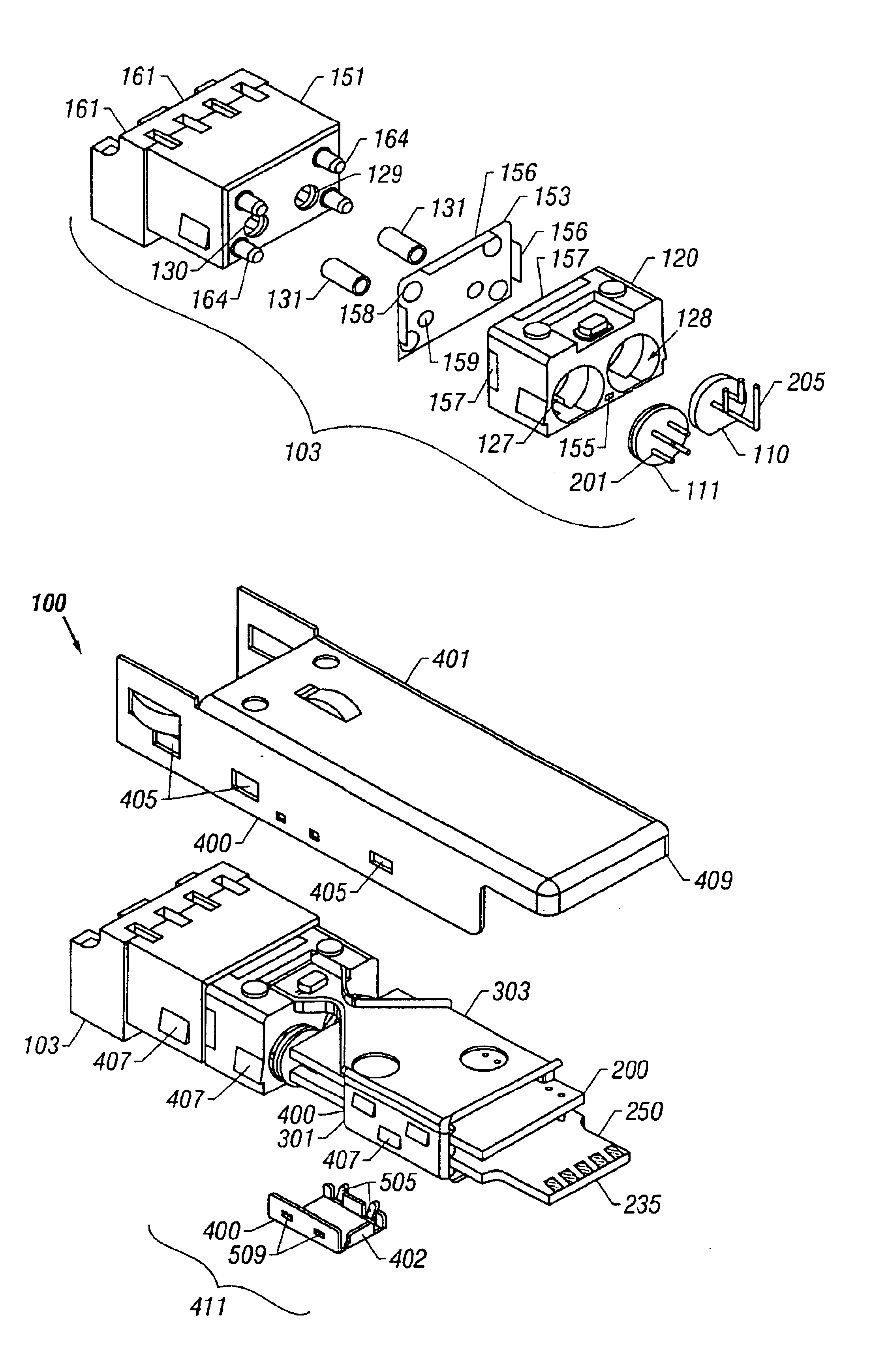
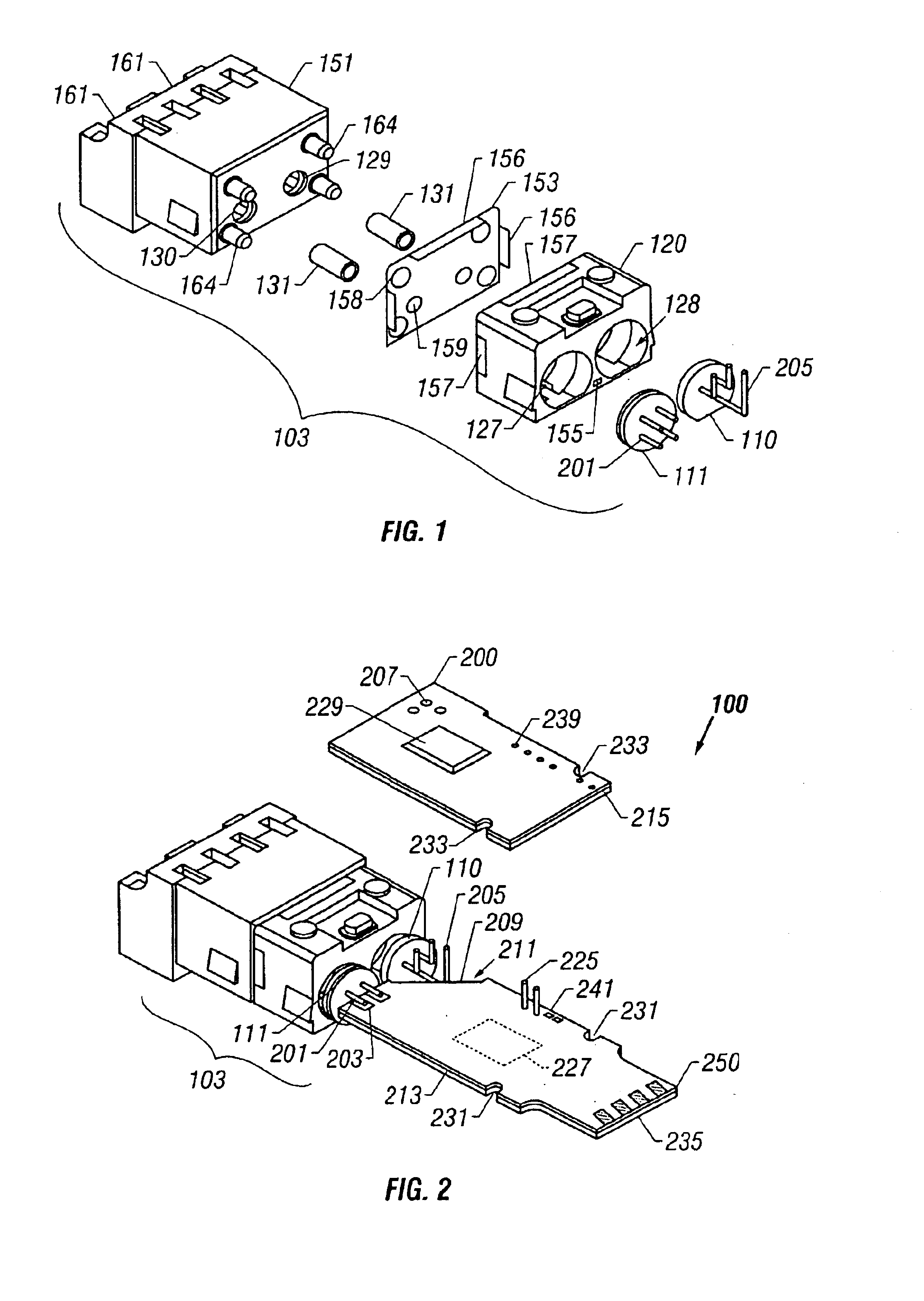
Referring now to FIG. 1, an exploded view of the optical element 103 of an embodiment of the present invention is illustrated. The optical element 103 include a nose 151, a pair of fiber ferrule sleeves 131, an electromagnetic interference shield plate 153, the electromagnetic interference plate 153 provides shielding to keep electromagnetic interference from leak...


PUM


Abstract

A fiber optic module for transferring data as pulses of light has an optical element with a first light transducer having a straddle mount lead and a second light transducer having a formed or bent signal lead. A first fiber optic receptacle optically couples to the first light transducer and a second fiber optic receptacle optically couples to a second light. A printed circuit board subassembly includes first and second printed circuit boards with an interconnection therebetween to couple to an electrical connector on the first. The first printed circuit board and second printed circuit boards are aligned so that the straddle mount leads couple to contacts on the first and the formed signal lead couple to contacts on the second. One or more electrical components in the fiber optic module process data for communication using light or photons over one or more optical fibers. An outer housing encloses the optical element subassembly and the printed circuit board subassembly. The electrical connector couples external electrical signals to the electrical components.

Description

FIELD OF THE INVENTIONThis invention relates generally to light coupling devices. More particularly, the invention relates to fiber optic modules.BACKGROUND OF THE INVENTIONFiber optic modules interface optical fibers to electronic circuitry transducing communication by light or photons with communication by electrical signals. A fiber optic module may be a fiber optic receiver, transmitter or transceiver including both receive and transmit functions. The fiber optic receiver, transmitter and transceiver each have optical elements (OE) and electrical elements (EE). The fiber optic transmitter OE includes an emitter (such as a semiconductor LED or Laser) mounted in a package and an optical coupling element for coupling light or photons from the OE into the optical fiber. The type of semiconductor laser (light amplification by stimulated emission of radiation) may be a vertical cavity surface emitting laser (VCSEL). The fiber optic receiver OE includes a photodetector (such as a photo...

Claims


Application Information

Patent Timeline
IPC IPC(8): G02B6/42H04B10/00H05K1/14H05K1/02
CPCG02B6/4204G02B6/4214G02B6/4246G02B6/4292H04B10/801G02B6/4277H05K1/14H05K1/0274
Inventor WEI, CHENG PINGDAIR, EDWIN D.
Owner JDS UNIPHASE CORP
Why Eureka
Try Eureka