Methods and apparatus for testing a clock signal

a clock signal and clock signal technology, applied in the direction of testing circuits, instruments, pulse characteristics measurements, etc., can solve the problems of inability to accurately detect the presence of such anomalies, the existence of clock signals that are irregular, and the computer system is prone to malfunction and/or useless, etc., to achieve various levels of accuracy and build the operating margin

Inactive Publication Date: 2005-03-29
CISCO TECH INC
View PDF12 Cites 14 Cited by
  • Summary
  • Abstract
  • Description
  • Claims
  • Application Information

AI Technical Summary

Benefits of technology

In one arrangement, the output circuit includes an RC circuit having an input coupled to the comparison circuit, and an output that provides a tuned signal based on the comparison signal. Such a circuit ...

Problems solved by technology

Unfortunately, there are deficiencies to computers which simply include a clock detection circuit for detecting the presence (or loss) of a clock signal.
In particular, such a detection circuit may indicate the presence of a clock signal even though the clock signal has anomalies which prevent the computer from operating properly.
However, the clock signal may have irregularities such as delayed or missing pulses.
In an environment requiring a high speed system clock (e.g., Gigabit Ethernet applications), a clock with such deficiencies essentially renders the computer system prone to malfunction and/or useless.
Moreover, if the delayed or missing pulses o...

Method used


Image

  • Methods and apparatus for testing a clock signal
  • Methods and apparatus for testing a clock signal
  • Methods and apparatus for testing a clock signal

Examples


Embodiment Construction

The invention is directed to techniques for testing a clock signal by comparing different portions of that clock signal to each other. Such techniques enable the detection of clock signal irregularities such as a clock signal having missing pulses or having occasional delayed pulses. Accordingly, these techniques can be used to insure the quality of the clock.

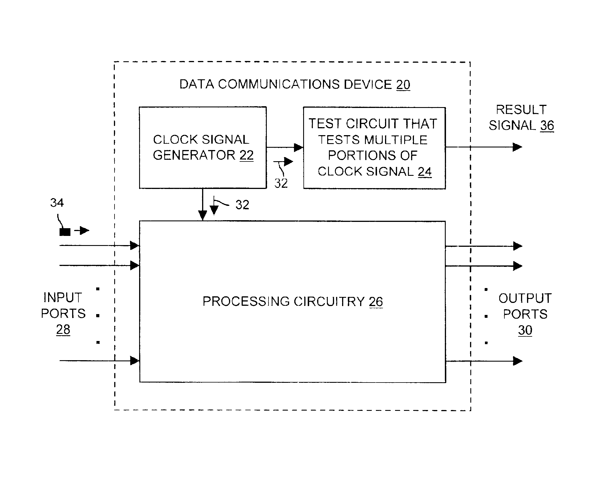
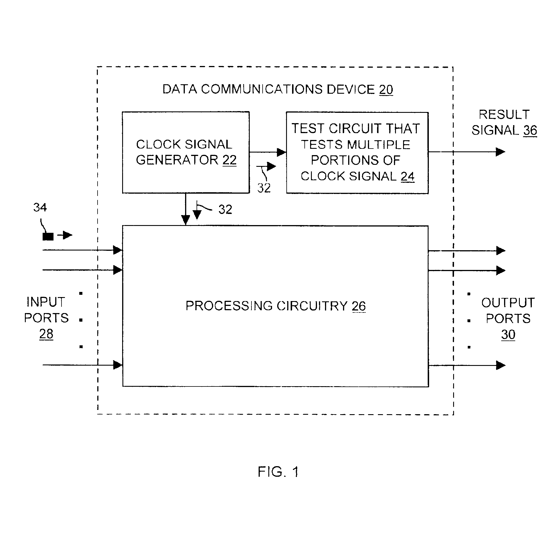
FIG. 1 shows a data communications device 20 which is suitable for use by the invention. The data communications device 20 includes a clock signal generator 22, a test circuit 24, and processing circuitry 26. The data communications device 20 further includes a set of input ports 28, and a set of output ports 30.

During operation, the clock signal generator 22 generates a clock signal 32 (e.g., a 125 MHz square wave, a 25 MHz square wave, etc.) which is received by both the test circuit 24 and the processing circuitry 26. The processing circuitry 26 receives data elements of 34 (e.g., packets, cells, frames, etc.) through the se...


PUM


Abstract

Techniques test a clock signal by comparing different portions of that clock signal to each other. Such techniques enable the detection of a clock signal having anomalies such as missing pulses or occasional delayed pulses. In one arrangement, a data communications device has a clock signal generator, processing circuitry and a test circuit, both of which are coupled to the clock signal generator. The clock signal generator provides a clock signal. The processing circuitry uses the clock signal to receive data elements on a set of input ports, and to transmit the data elements on a set of output ports. The test circuit includes a node that receives the clock signal, a comparison circuit that provides a comparison signal based on a comparison between the clock signal and a delayed copy of the clock signal, and an output circuit that provides a result signal based on the comparison signal.

Description

BACKGROUND OF THE INVENTIONA typical computer includes a clock generator that provides accurately timed pulses for synchronization. Some clock generators work off of a crystal, i.e., a natural or synthetic piezoelectric or semiconductor material which controls the frequency of oscillation of the clock signal. For example, some computers include a crystal driven clock generator that provides a system clock, i.e., a global clock signal which guides computer operations.Clock generators are susceptible to failure. For example, a clock generator may stop providing pulses. Such a failure can be caused by an extreme operating environment (e.g., an excessive heat or humidity condition). Such a failure could also be caused by other factors such as gradual aging of the clock generator components (e.g., the crystal), poor quality components, or a manufacturing defect, etc.Some computers include a clock detection circuit that monitors the operation of the clock generator. Such a circuit typical...

Claims


Application Information

Patent Timeline
IPC IPC(8): G01R29/02
CPCG01R29/02
Inventor DIAB, WAEL
Owner CISCO TECH INC
Why Eureka
Try Eureka