
Memory control device and method

a memory control and memory controller technology, applied in the field of control devices and methods, can solve the problems of time and effort wasted in error checking and correction of error permissible data, data accessed by instruction addresses must be error checked, and system stability is maintained, so as to achieve the effect of not wasteing time and effort in error checking and correction

Inactive Publication Date: 2005-03-29
VIA TECH INC
View PDF9 Cites 0 Cited by
  • Summary
  • Abstract
  • Description
  • Claims
  • Application Information

AI Technical Summary

Benefits of technology

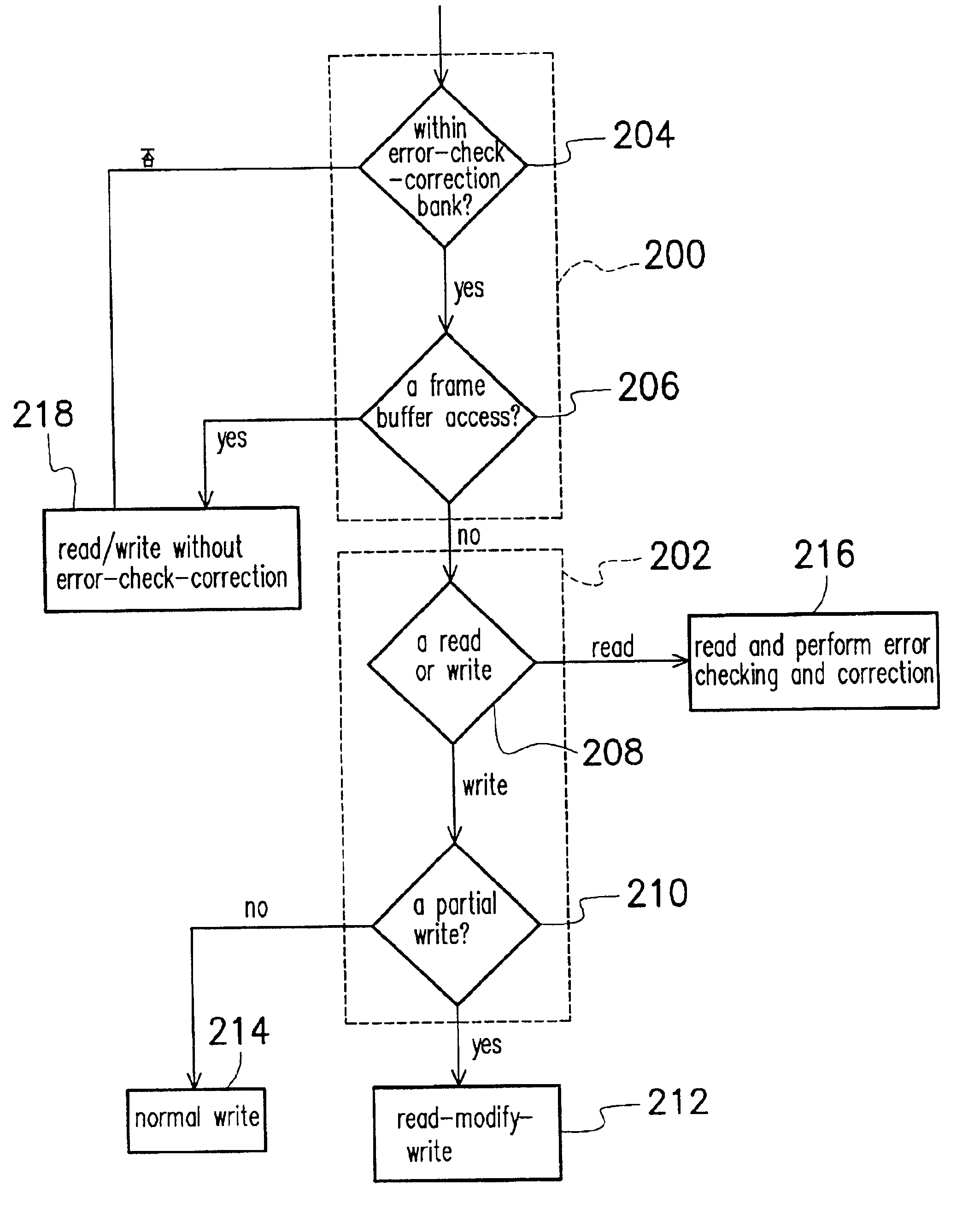
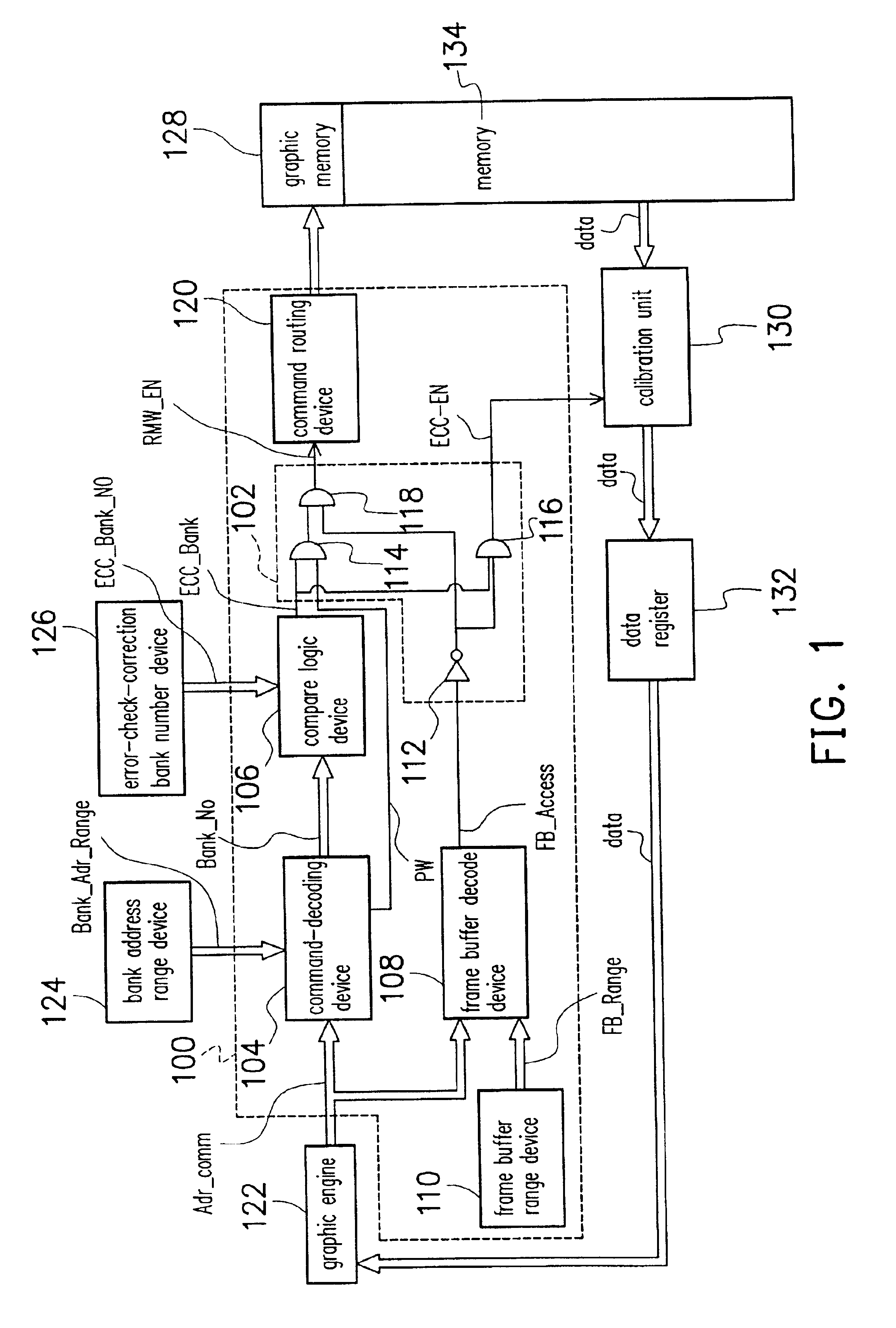
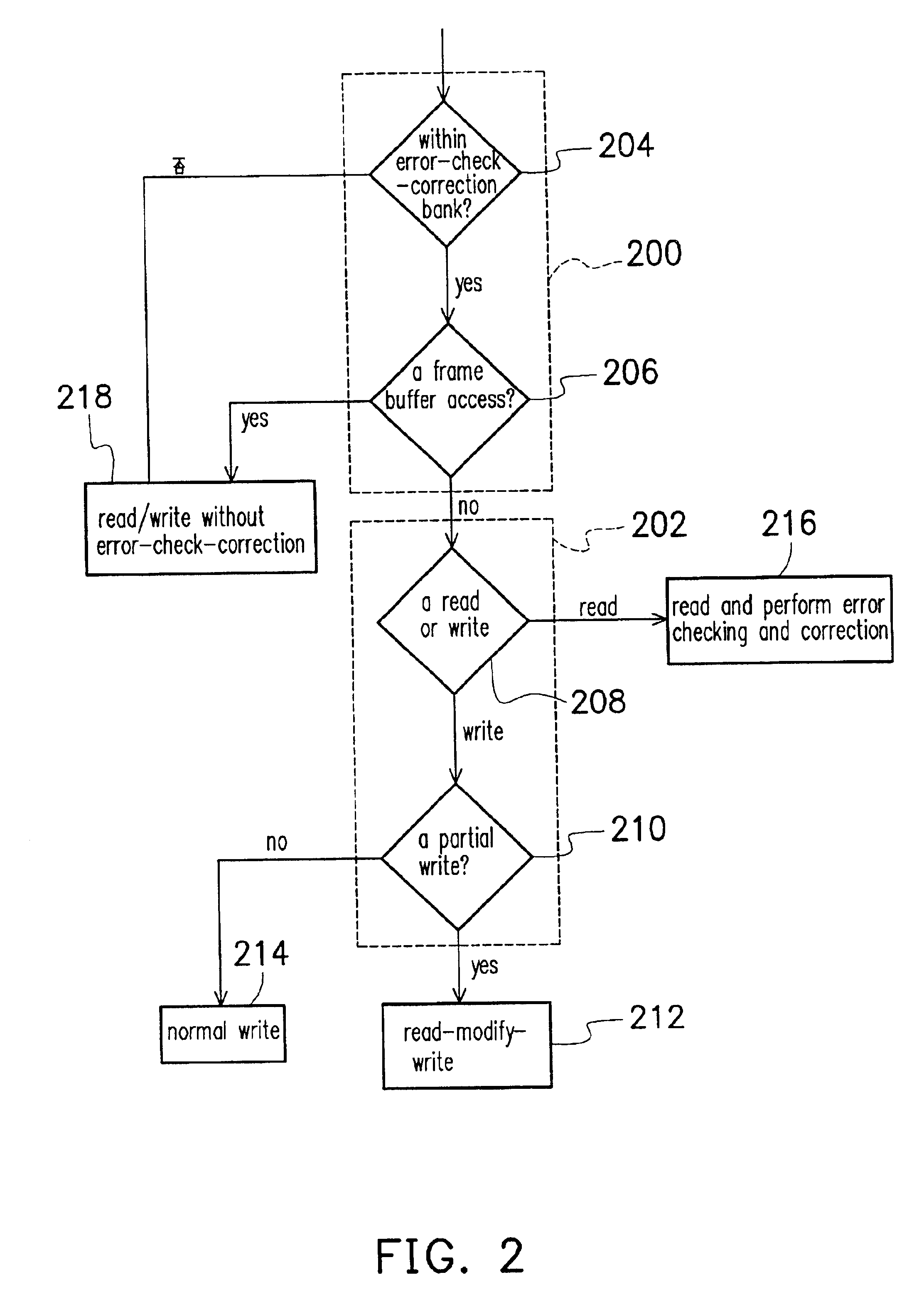
The present invention provides a memory control device and method for controlling memory operation. The device includes a command decoding device, a compare logic device, a decision device, a frame buffer decode device, a frame buffer range device and a command routing device. The device can determine the bank within the memory in which the data pointed to by the command address resides and check if the data falls within the range of the graphic memory. The device can also check if the data falls within the range of memory having an error-check-correction function and output an error-check-correction bank signal. The method includes dividing the memory access command into two portions, checking the command code, and executing a memory data read / write operation without any error checking and correction if the data falls within a graphic memory range having error-check-correction function. The technical effects of this invention include accurate data and stable system stability.

Problems solved by technology

For example, if data are sent to the graphic engine for display purpose only, error checking may be skipped.
Nevertheless, some data accessed by an instruction address must be error checked.
Hence, processing time is wasted in accurate checking and correcting of error permissible data such as graphic memory data.

Method used


Image

  • Memory control device and method
  • Memory control device and method
  • Memory control device and method

Examples


Embodiment Construction

Reference will now be made in detail to the present preferred embodiments of the invention, examples of which are illustrated in the accompanying drawings. Wherever possible, the same reference numbers are used in the drawings and the description to refer to the same or like parts.

FIG. 1 is a schematic architectural layout of a memory control device according to one preferred embodiment of this invention. As shown in FIG. 1, the memory control device 100 includes a decision device 102, a command decoding device 104, a compare logic device 106, a frame buffer decode device 108, a frame buffer range device 110 and a command routing device 120. In this embodiment, memory access command for controlling a memory unit 134 is initiated from a graphic engine device 122. In general, a memory access command at least includes two portions, an access address and a command code.

When the graphic engine 122 issues a memory access command (Adr-Comm) to the command decoding device 108, the memory ac...


PUM


Abstract

A memory control device and a method of controlling memory transfer. The memory control device has a command decoding device, a compare logic device, a decision device, a frame buffer decode device, a frame buffer range device and a command routing device. The frame buffer range device is used to determine if the access address pointed to a graphic memory. The command-decoding device and the compare logic device are used to determine if the access address points to a memory bank range having an error-check-correction function. The decision device is used to determine if the access address points to a memory bank range having error-check-correction function but outside the graphic memory range. If the access address points to a memory bank range having error-check-correction function but outside the graphic memory range, a memory access command with error checking and correction of data is executed.

Description

CROSS-REFERENCE TO RELATED APPLICATIONThis application claims the priority benefit of Taiwan application serial no. 90111531, filed on May 15, 2001.BACKGROUND OF THE INVENTION1. Field of InventionThe present invention relates to a control device and method. More particularly, the present invention relates to a memory control device and method.2. Description of Related ArtConventionally, graphic memory and main memory of a system are separately controlled. In general, a graphic engine manages the graphic memory while a north bridge controls the error check correction of the main memory. Hence, graphic memory and main memory are unrelated to each other. However, due to rapid progress in technologies, memory speed has increased correspondingly. In one type of design known as unified memory architecture (UMA), the graphic engine merges with the North Bridge while the graphic memory merges with the main memory. Instruction data to be accessed by an address is normally stored inside the m...

Claims


Application Information

Patent Timeline
Patent Type & Authority Patents(United States)
IPC IPC(8): G11C8/00G11C8/12
CPCG11C8/12
Inventor CHANG, ERIC YEAN-LIUHUANG, HSIANG-I
Owner VIA TECH INC
Learn More