Wheel balance weight and process for manufacturing the same

a technology of balance weight and wheel, which is applied in the direction of rotating body balancing, mechanical equipment, transportation and packaging, etc., can solve the problems of imbalance in the wheel, large vibration, noise, etc., and achieve the effect of less load on the environment, and easy processing

Inactive Publication Date: 2005-04-05
HONDA MOTOR CO LTD +1
View PDF15 Cites 19 Cited by
  • Summary
  • Abstract
  • Description
  • Claims
  • Application Information

AI Technical Summary

Benefits of technology

In accordance with the present process for manufacturing the present wheel balance weight, it is possible to manufacture the present wheel balance weight which comprises the weight being composed of zinc or a zinc-based alloy. Specifically, zinc or a zinc-

Problems solved by technology

In a wheel-assembled state; namely: in a state where a tire of an automobile, or the like, is assembled with a wheel, there arises a drawback in that, as the imbalance enlarges in the peripheral direction around the rotary shaft of the wheel assembly as well as in the direction

Method used


Image

  • Wheel balance weight and process for manufacturing the same
  • Wheel balance weight and process for manufacturing the same
  • Wheel balance weight and process for manufacturing the same

Examples


examples

The present invention will be hereinafter described in detail with reference to specific examples.

example no.1

Example No. 1

Manufacture of Wheel Balance Weight

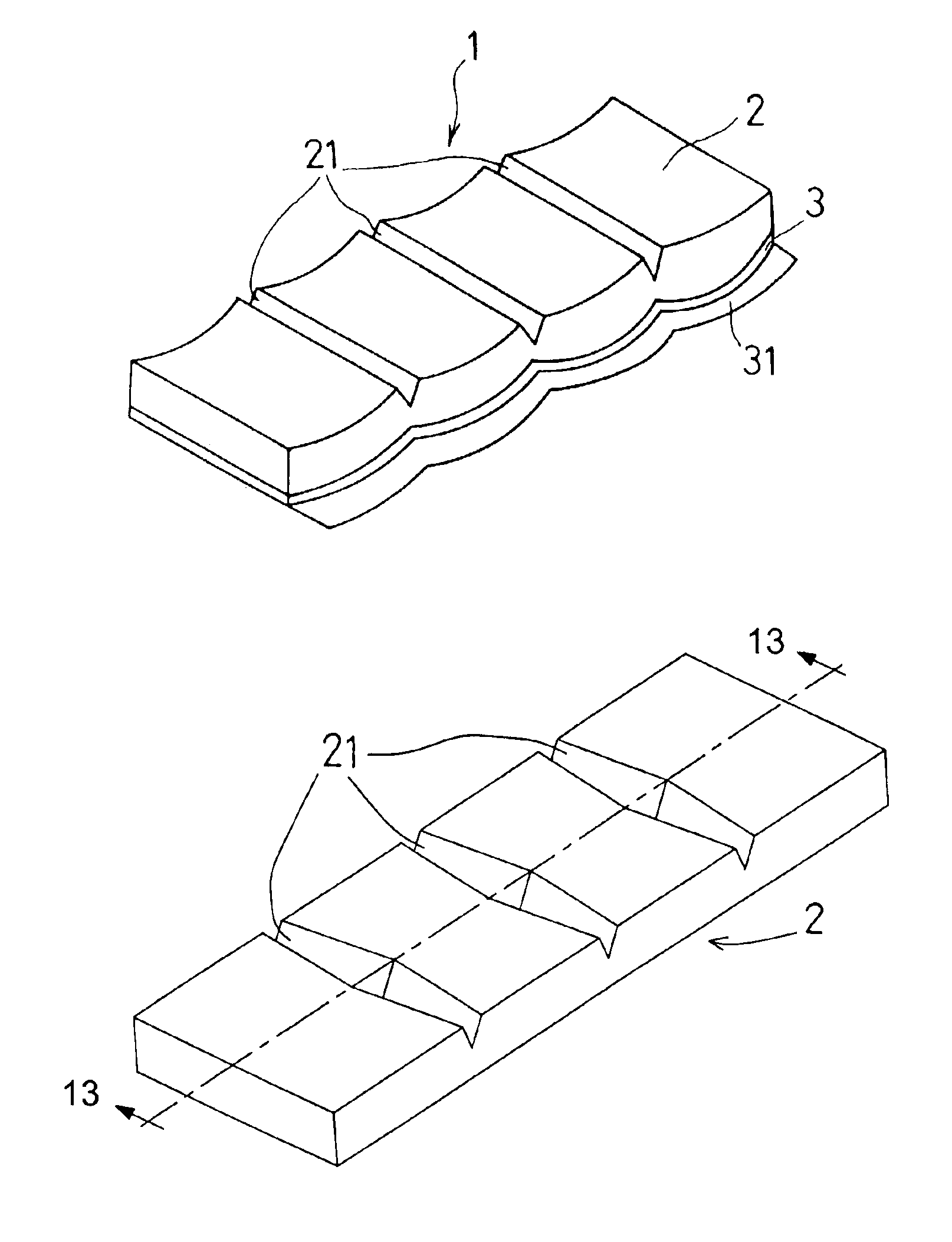
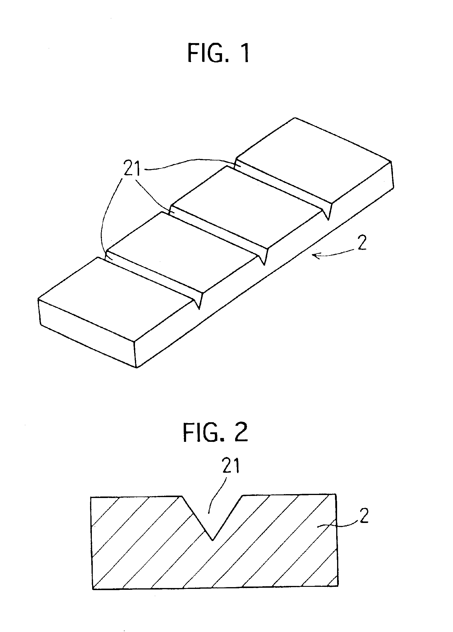
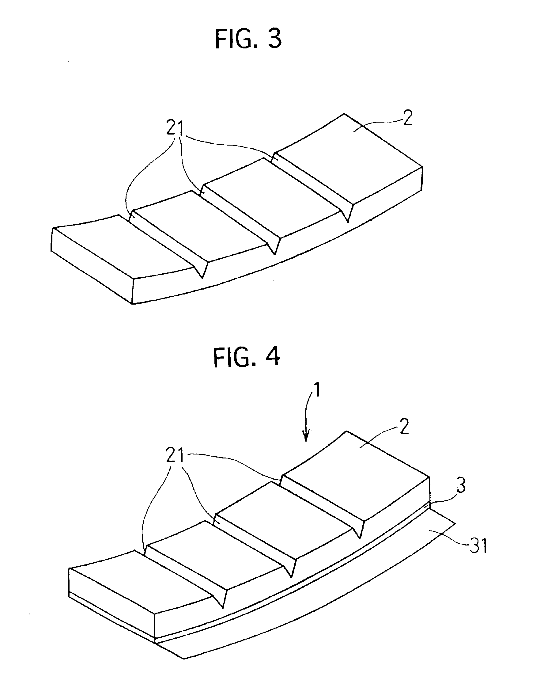
In Example No. 1, a wheel balance weight as illustrated in FIGS. 1 through 4 was manufactured. The manufacturing method of the wheel balance weight of Example No. 1 will be hereinafter described with reference to FIGS. 1 through 4.

First of all, metallic materials, such as metallic zinc, metallic tin, metallic copper and metallic aluminum, were weighed by a predetermined amount, respectively. Then, the metallic materials were charged into a crucible, and were heated. Thus, the metallic materials were melted to prepare a molten alloy. According to an weight analysis, the molten alloy contained zinc in an amount of 95% by weight, tin in an amount of 0.01% by weight, copper in an amount of 1% by weight, aluminum in an amount of 3.84% by weight, and the inevitable impurities in an amount of less than 0.15% by weight.

Subsequently, the molten alloy was poured into a mold to manufacture a strip-shaped weight 2. Note that a plurality of grooves...

example no.2

Example No. 2

In Example No. 2, a wheel balance weight 1 as illustrated in FIG. 6 was manufactured. The wheel balance weight 1 is provided with a plate-shaped weight 2 in which grooves 21 having a letter “U”-shaped cross section were formed in one of the opposite surfaces.

In the wheel balance weight 1 of Example No. 2, the weight 2 was manufactured by press working.

Specifically, a zinc alloy plate which had the same alloy composition as that of the weight 2 of the wheel balance weight 1 of Example No. 1 was first cut to a strip shape. Then, the strip-shaped zinc alloy plate was pressed by a punch which had a predetermined shape to manufacture the weight 2 which was provided with the grooves 21 in one of the opposite surfaces of the strip-shaped zinc alloy plate. The grooves 21 herein had a letter “U”-shaped cross section, and crossed in the width-wise direction of the strip-shaped weight 2.

Subsequently, one of the opposite adhesive surfaces of a double-sided tape 2 was adhered onto t...


PUM


Abstract

A wheel balance weight includes a weight and an installation member. The weight is composed of at least one member selected from the group consisting of zinc and a zinc-based alloy, is formed as a substantially strip shape having a substantially uniform thickness, and has opposite surfaces and at least a groove. The groove is formed in at least one of the opposite surfaces of the weight, and crosses in the width-wise direction of the weight. The installation member is adapted for installing the weight to a rim in a wheel. Since the weight is composed of zinc or a zinc-based alloy, environments are inhibited from being polluted when the wheel balance weight is abolished. Moreover, it is possible to manufacture the wheel balance weight at reduced costs and install it to wheels with ease.

Description

BACKGROUND OF THE INVENTION1. Field of the InventionThe present invention relates to a wheel balance weight. In particular, it relates to a wheel balance weight which is installed to an inner peripheral surface of a rim in a wheel of a vehicle.2. Description of the Related ArtIn a wheel-assembled state; namely: in a state where a tire of an automobile, or the like, is assembled with a wheel, there arises a drawback in that, as the imbalance enlarges in the peripheral direction around the rotary shaft of the wheel assembly as well as in the direction of the rotary shaft of the wheel assembly, the vibrations, noises, and the like, generate when driving a vehicle.The vibrations, noises, and soon, result from the imbalance in the wheel. Accordingly, the wheel is equipped with a wheel balance weight, which can cancel the imbalance. The installation position of the wheel balance weight to the wheel and the mass of the wheel balance weight are determined by measuring the imbalance of the w...

Claims


Application Information

Patent Timeline
IPC IPC(8): F16F15/00F16F15/32B21D53/30
CPCF16F15/328
Inventor YOSHIMURA, YASUNORISUZUKI, EIJIICHIMURA, YOSHIHIROINABA, YOICHIROYAMAGUCHI, YUTAKA
Owner HONDA MOTOR CO LTD
Why Eureka
Try Eureka