Process for manufacturing highly stressed composite parts

Inactive Publication Date: 2005-04-05
CONCEPTION & DEV MICHELIN SA
View PDF14 Cites 17 Cited by
  • Summary
  • Abstract
  • Description
  • Claims
  • Application Information

AI Technical Summary

Benefits of technology

It is firstly the state of prepolymerization achieved, which is perfectly controlled due to prepolymerization by ionizing irradiation, and secondly the subdivision into several layers of low thickness, which make it possible to impose both relatively small radii of curvature without major residual stresses resulting within each length, without buckling of the fibers appearing during stacking, and without dispersion of the fibers occurring in the cross-section of the stack, in particular dispersions within the thickness. The elastic return of the stacks thus produced to a configuration in which the internal stresses would be zero is relatively slight, which makes it possible relatively easily to maintain mechanically or to freeze the deformation imposed without interf

Problems solved by technology

However, the compression-molding process is incompatible with the use of long reinforcement fibers.
For this reason, it is not possible to consider producing parts which are mechanically very highly stressed by this process.
But apart from the fact that the variety of forms is very limited, it is difficult to position the fibers entirely in the thickness of the manufactured wall.
It is also difficult to maintain a constant proportion of fibers throughout the thickness of the wall.
However, the problem of such treatment is that it is difficult to control the stage at which what shall be named “a prepolymerization” is brought about (initial partial polymerization).
Of course, the more advanced the prepolymerization and the better the fibers are maintained, but the more difficult it becomes to change the shape during later molding of the preform.
Moreover, it is furthermore very diff

Method used


Image

  • Process for manufacturing highly stressed composite parts
  • Process for manufacturing highly stressed composite parts
  • Process for manufacturing highly stressed composite parts

Examples


Embodiment Construction

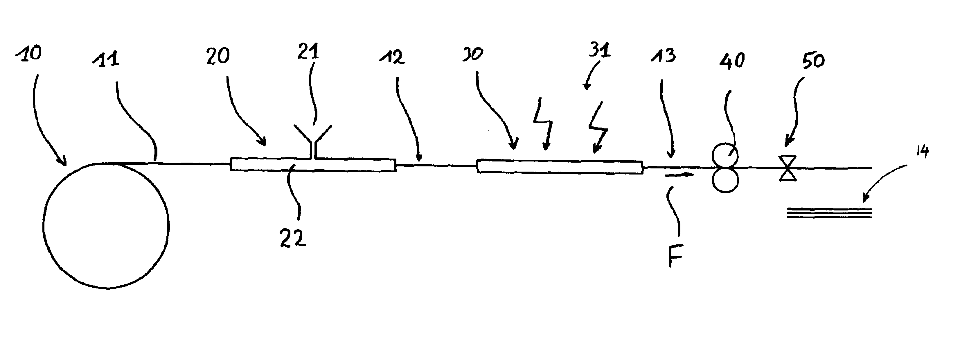
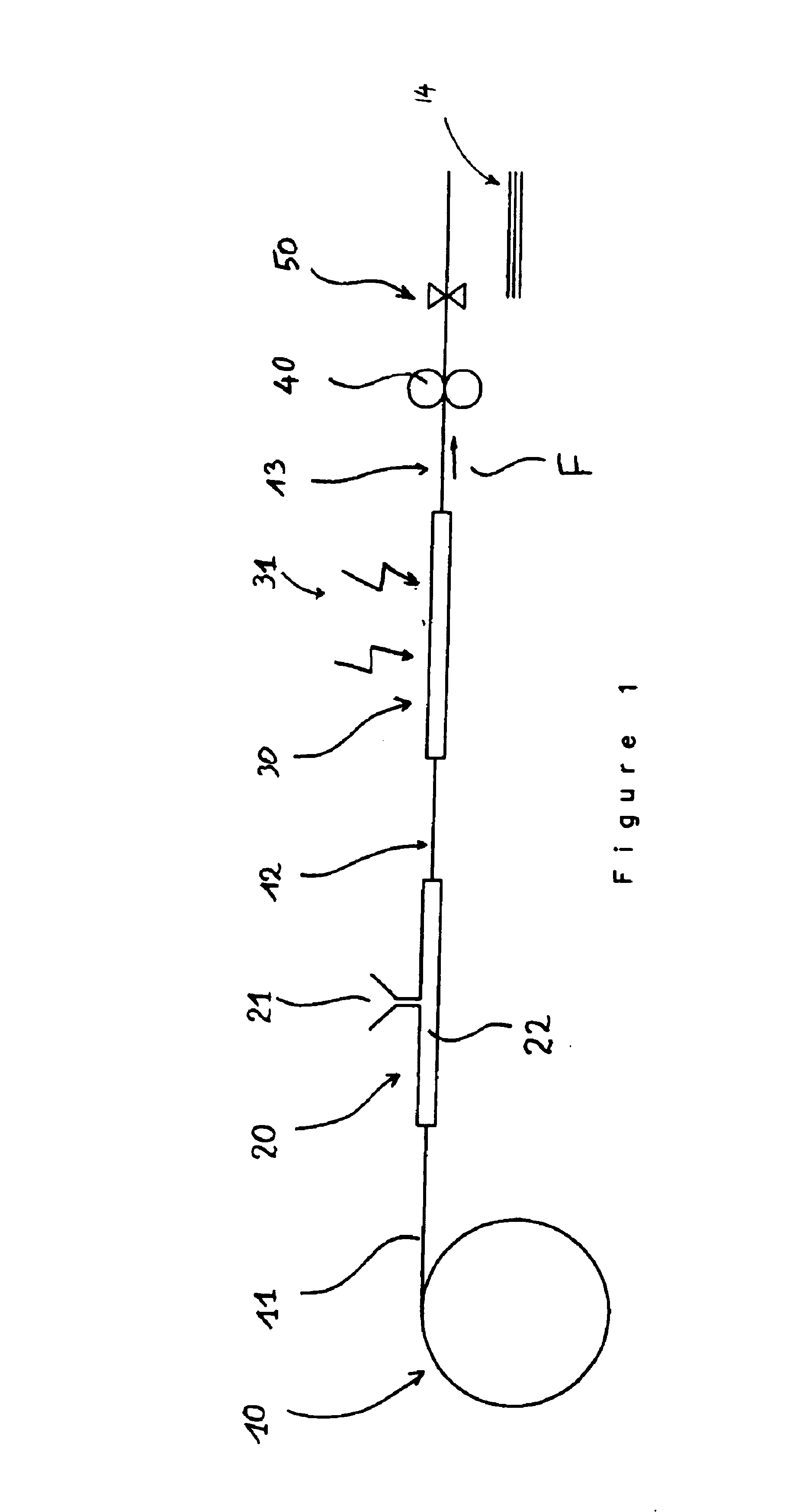
FIG. 1 shows a reel 10 containing a spun yarn 11 which, in the example illustrated, is formed of glass fibers. There is then shown an impregnation device 20 comprising a reservoir 21 containing a composition based on a hardenable resin and a -photoinitiator appropriate to the irradiation by which said composition will be treated. The impregnation device 20 comprises an impregnation chamber 22. There results from this a pre-impregnated material 12 which is introduced into a prepolymerization device 30, in which the pre-impregnated material 12 is prepolymerized by ionizing irradiation, the treatment being carried out with oxygen excluded. As for the irradiation 31 to which the composition is exposed, its wavelength is typically less than 450 nanometers, preferably between 300 nm and 450 nm. For example, an ultraviolet lamp may be used. Rollers 40 drive the precomposite 13 obtained in the direction of the arrow F. Finally, shears 50 make it possible to take lengths 14 from the continuo...


PUM

PropertyMeasurementUnit
Temperatureaaaaaaaaaa

Abstract

A process for making a composite product in which reinforcement fibers are subjected to a composition based on a thermohardening resin and a photoinitiator appropriate to the irradiation by which the composition is to be treated. The resulting pre-impregnated material is introduced into a prepolymerization device, in which the pre-impregnated material is prepolymerized by appropriate irradiation. Lengths of the precomposite are applied to a support, the shape of which is dictated by the shape of one face of the composite part which is to be made, and are stacked one on another in a suitable number and placed snugly against the shape of the support, and the stack is subjected to final molding at a suitable pressure and temperature in order to polymerize the resin and to join the different lengths of precomposite.

Description

BACKGROUND OF THE INVENTIONThe present invention relates to processes for manufacturing composite parts, in particular in the case of parts having complex shapes. It relates more particularly to composite parts which are subject to very high mechanical stress.One process for manufacturing composite parts consists in compression-molding a paste under high pressures, then effecting complete polymerization before demolding. The paste has been prepared beforehand, and comprises a mixture of resin and short fibers. This process is very widely used owing to its suitability for the manufacture of parts having complex shapes and to its high productivity. However, the compression-molding process is incompatible with the use of long reinforcement fibers. For this reason, it is not possible to consider producing parts which are mechanically very highly stressed by this process.Other techniques are known which make it possible to use long reinforcement fibers. One of these techniques is referre...

Claims


Application Information

Patent Timeline
IPC IPC(8): B29C35/10B29C35/08B29C70/10B29C70/20B29B11/02B29B11/16B29C43/02B29C70/06B32B5/00B32B5/28B32B25/10B32B37/10B32B37/16C08F2/44C08F2/50C08F283/10C08F290/06H05K1/03H05K3/00
CPCB29C35/08B29C35/10B29C70/20Y10T156/1043H05K1/0366H05K3/0014
Inventor MEUWLY, ROGERHINC, HENRIMOUSTY, HERVETORNARE, MARCEL
Owner CONCEPTION & DEV MICHELIN SA
Why Eureka
Try Eureka