
Methods and apparatus for oil demulsification and separation of oil and suspended solids from produced water

a technology of suspended solids and demulsification method, which is applied in the direction of settling tank feed/discharge, machine/engine, and well accessories, etc., can solve the problems of affecting the quality of produced water

Inactive Publication Date: 2005-04-05
HYDROTREAT
View PDF34 Cites 51 Cited by
  • Summary
  • Abstract
  • Description
  • Claims
  • Application Information

AI Technical Summary

Benefits of technology

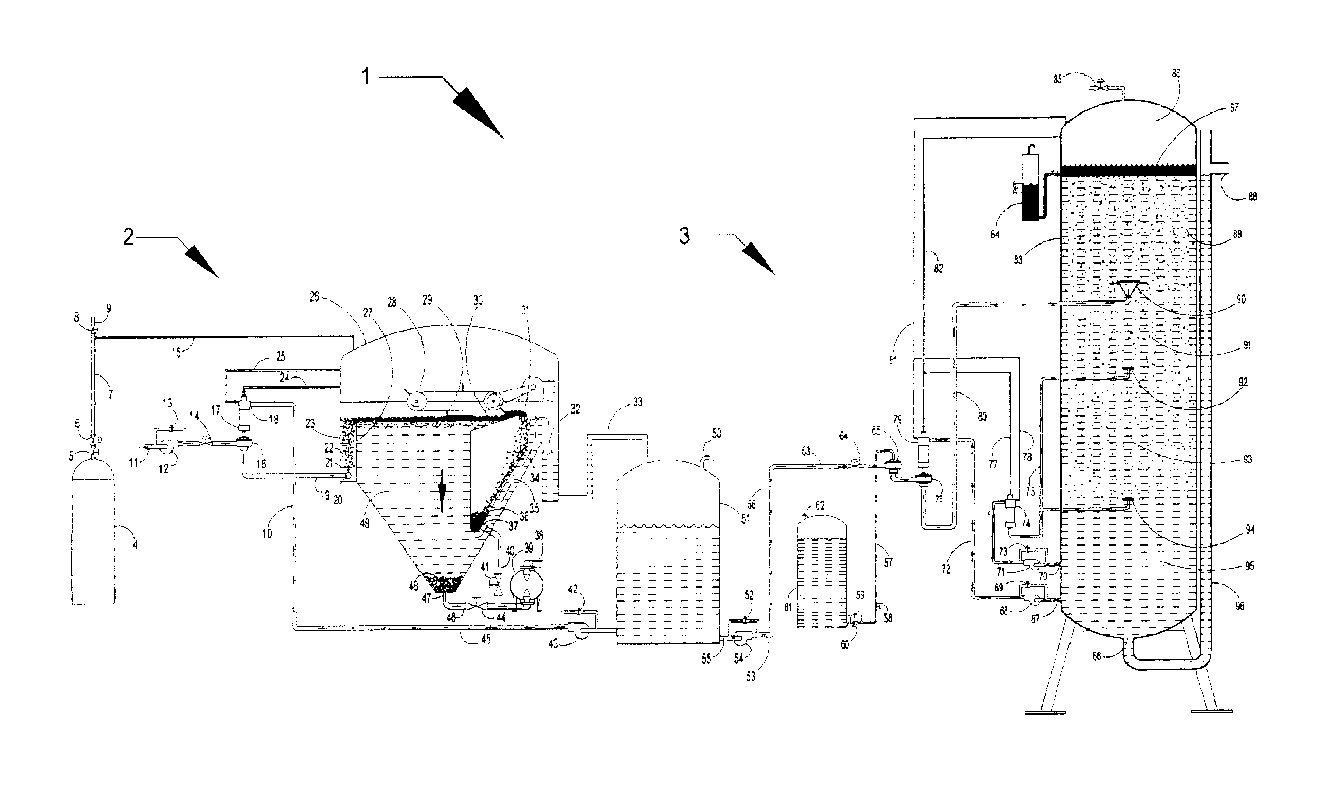
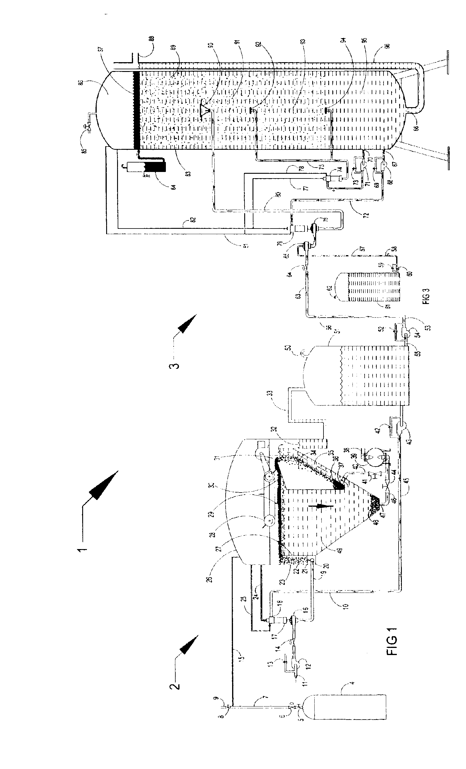
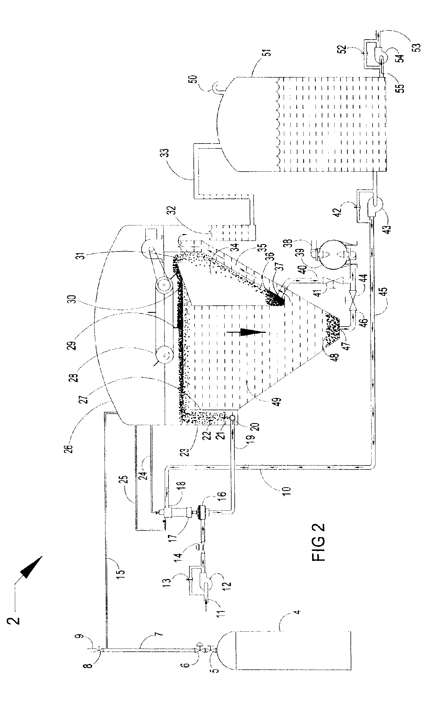
"The present invention relates to methods and apparatus for treating produced water in oil and gas wells. The invention includes a dissolved gas floatation clarifier system and an oil demulsification and separation system. The dissolved gas floatation clarifier system removes suspended solids and some emulsified oil from the produced water using microscopic bubbles generated by dissolved gas. The oil demulsification and separation system then removes the remaining emulsified oil. The system includes associated piping and equipment such as a water inlet, pressure regulator, dissolved gas generator, recycle pressure aeration system, storage tank, and pumps. The invention allows for efficient treatment of produced water to reduce the amount of oil and suspended solids released into the environment."

Problems solved by technology

Most of the deficiencies of the present dissolved gas floatation systems are in the quality of the bubbles produced, size and cost of the apparatus used to generate the bubbles, method of introducing the bubbles into the stream of water to be treated, and the success of mixing and dispersing the demulsifying agents added by existing apparatus used.
If the oil-water mixture is stirred vigorously, it will take some time for them to separate again.
The emulsified oil droplets may also be mixed with finely coated solid particles from a number of materials to further complicate the emulsion.
While the problem exists anywhere oil and gas is produced and processed, an offshore platform is not readily accessible and oil and gas production could perhaps be from as many as thirty wells and the quantity of produced water may be enormous.
The remaining contamination may still exceed that allowed for disposal.
The cost of using chemical demulsifiers in the large volumes of produced water would be enormous and may outweigh the benefits realized.

Method used


Image

  • Methods and apparatus for oil demulsification and separation of oil and suspended solids from produced water
  • Methods and apparatus for oil demulsification and separation of oil and suspended solids from produced water
  • Methods and apparatus for oil demulsification and separation of oil and suspended solids from produced water

Examples


Embodiment Construction

Illustrative embodiments of the invention are described below as they might be employed in the use of the methods and apparatus for oil demulsification and separation of suspended solids and oil from produced water. In the interest of clarity, not all features of an actual implementation are described in this specification. It will of course be appreciated that in the development of any such actual embodiment, numerous implementation-specific decisions must be made to achieve the developers' specific goals, such as compliance with system-related and business-related constraints, which will vary from one implementation to another. Moreover, it will be appreciated that such a development effort might be complex and time-consuming, but would nevertheless be a routine undertaking for those of ordinary skill in the art having the benefit of this disclosure.

Further aspects and advantages of the various embodiments of the invention will become apparent from consideration of the following d...


PUM

PropertyMeasurementUnit
pressureaaaaaaaaaa
outer diameteraaaaaaaaaa
diameteraaaaaaaaaa

Abstract

Methods and apparatus for demulsifying oil in water by dilution and impact, and for separation of the oil and suspended solids by dissolved gas floatation, are described. A produced water treating system is also described. The produced water treating system may include a dissolved gas floatation clarifier system, an oil demulsification system, and a separation system. A demulsification subsystem is also described. The apparatus may include a liquid-liquid fluid mixer and a gas generator.

Description

BACKGROUND OF THE INVENTION1. Field of the InventionThe present invention relates to methods and apparatus for demulsifying oil in water by dilution and impact, and for separation of the oil and suspended solids by dissolved gas floatation. Saltwater brought to the surface with gas and oil from underground production wells is commonly referred to as “produced water.” The methods and apparatus of the present invention are particularly suitable for demulsifying oil in produced water using dissolved methane or dissolved carbon dioxide as a diluted and for separating the oil and suspended solids from the produced water also using dissolved methane or dissolved carbon dioxide for floatation.2. Description of Related ArtThe methods and apparatus for dissolving gases in liquids disclosed in patent application Ser. No. 09 / 897,496, filed Jun. 12, 2001, now U.S. Pat. No. 6,669,843, issued Dec. 30, 2003, in the name of Johnny Amaud and assigned to the same assignee as the present application w...

Claims


Application Information

Patent Timeline
Patent Type & Authority Patents(United States)
IPC IPC(8): B01D21/24B03D1/14E21B43/34E21B43/12E21B43/16B01D17/035B01D17/038B01D17/12B01D65/00
CPCB01D21/2433B01D21/245E21B43/122E21B43/128E21B43/129B03D1/1431E21B43/34E21B43/166B03D1/1475B03D1/1462B01D21/0084B01D21/34E21B43/35
Inventor ARNAUD, JOHNNY
Owner HYDROTREAT
Learn More