
Circulating treatment regeneration process of oil-containing VOCs exhaust gas spray absorption medium

A technology of absorbing medium and circulating treatment, which is applied in the field of environmental engineering, can solve the problems of equipment blockage, incomplete oil separation, and low efficiency of spraying equipment, etc., and achieve the effect of enhancing the purification effect and preventing iron filings from compacting

Inactive Publication Date: 2019-02-01
苏州智为环境科技有限公司
View PDF4 Cites 0 Cited by
  • Summary
  • Abstract
  • Description
  • Claims
  • Application Information

AI Technical Summary

Problems solved by technology

The problem with the "oil separation + precipitation" method is that the oil separation is not complete and the dissolved pollutants cannot be removed; during the spraying process, the oil in the exhaust gas is in full contact with the spray medium, and most of the oil enters the spray in the form of emulsified oil. In the spray medium, since the oil separation method uses the principle of gravity to separate the oil, the emulsified oil cannot be removed by the oil separation method at this time; the precipitation method can only remove the solid matter in the spray medium and a small part of the dissolved state Pollutants; therefore, the traditional method of treating the spray medium is not completely removed, resulting in a substantial reduction in the function of the spray medium during the operation of the system, and the effect of the system cannot be guaranteed for a long time
[0003] "Oil separation + precipitation" can only isolate non-emulsified oil, but cannot effectively remove emulsified oil in the spray medium. At the same time, only solid pollutants can be removed through sedimentation tanks, and dissolved pollutants cannot be removed. Causes low efficiency during the use of spray equipment, long-term equipment blockage and secondary pollution of spray media

Method used


Image

  • Circulating treatment regeneration process of oil-containing VOCs exhaust gas spray absorption medium

Examples


Embodiment Construction

[0019] The following will clearly and completely describe the technical solutions in the embodiments of the present invention with reference to the accompanying drawings in the embodiments of the present invention. Obviously, the described embodiments are only some, not all, embodiments of the present invention. Based on the embodiments of the present invention, all other embodiments obtained by persons of ordinary skill in the art without making creative efforts belong to the protection scope of the present invention.

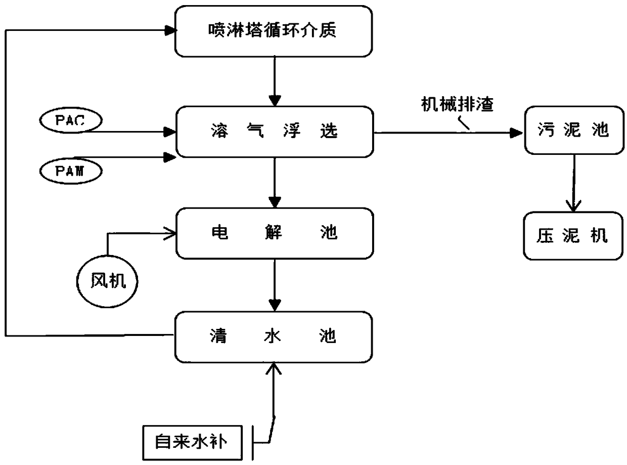
[0020] see figure 1 , the present invention provides a technical solution: oil-containing VOCs waste gas spray absorption medium circulation treatment regeneration process, including spray tower, dissolved air flotation tank, electrolytic tank, clear water tank and sludge tank, and a dissolved air tank is arranged under the spray tower Flotation tank, and the top side of the dissolved air flotation tank is connected to the sludge tank, the bottom of the dissol...


PUM


Abstract

The invention discloses a circulating treatment regeneration process of an oil-containing VOCs exhaust gas spray absorption medium. The process utilizes a spray tower, a dissolved air flotation cell,an electrolytic cell, a clean water tank and a sludge pool. The dissolved air flotation cell is arranged below the spray tower. The top side of the dissolved gas flotation cell is connected to the sludge pool. The bottom of the dissolved air flotation cell is connected with the electrolytic cell. The electrolytic cell is connected to the clear water tank. The clear water tank is connected to the spray tower. The process can produce initial ecological Fe<2+> and atom H through an electrochemical reaction under oxygenation conditions and the Fe<2+> and atom H have high chemical activity, can change the structures and characteristics of many organic substances, can realize organic matter chain breaking and ring opening, and can oxygenate and prevent iron scrapping in aeration. Fe<3+> generated by Fe<2+> oxidation is gradually hydrolyzed to form a Fe(OH)3 colloidal flocculant with high degree of polymerization, which can effectively adsorb and condensate the pollutants in the spray mediumto enhance the purification effect.

Description

technical field [0001] The invention relates to the technical field of environmental engineering, in particular to a regeneration process for oil-containing VOCs waste gas spray absorption medium circulation treatment. Background technique [0002] Usually, the treatment system for oily VOCs exhaust gas includes a spray tower to cool down the exhaust gas, remove dust and use the spray medium to absorb some pollutants. After the spray medium is used for a period of time, some dust and pollutants enter the spray medium, making the spray medium dirty and saturated; in conventional methods, the method of "oil separation + precipitation" is generally used to remove the solid matter in the spray medium. and dissolved pollutants are removed. The problem with the "oil separation + precipitation" method is that the oil separation is not complete and the dissolved pollutants cannot be removed; during the spraying process, the oil in the exhaust gas is in full contact with the spray m...

Claims


Application Information

Patent Timeline
Patent Type & Authority Applications(China)
IPC IPC(8): B01D53/14
CPCB01D53/1425B01D2257/708
Inventor 孔维辉
Owner 苏州智为环境科技有限公司
Learn More