
Method and device for treating and/or coating a surface of an object

Inactive Publication Date: 2005-04-05
SCHOTT SOLAR GMBH +1
View PDF4 Cites 27 Cited by
  • Summary
  • Abstract
  • Description
  • Claims
  • Application Information

AI Technical Summary

Benefits of technology

[0010]The object of the present invention is to develop a method and a device of the type described at the beginning that will allow adequate surface and / or spatial homogeneity of the area of the surface that is to be treated, or of the coating to be applied to the surface, to be achieved. A further object of the invention is to provide a high level of efficiency in the coating of the surface, i.e. an adequate ratio of coating rate to gas flow. In addition, a well-calculated gas direction and gas flow are to be ensured via simple means.
[0013]With the teaching of the present invention, the disadvantages of the current state of the art are avoided, while at the same time considerable advantages are achieved: These include the removal of used gas from the reaction chamber immediately following reaction, and the improved exploitation of the unused portion of the gas via recycling; a further advantage is the homogeneity of the deposition rate with a non-rotating substrate.
[0014]In comparison with methods in which the gas flow is directed horizontally toward a non-rotating substrate surface, with a deposited layer a more homogeneous deposition rate and thus a more homogeneous coating thickness and doping are achieved. In comparison with known methods in which the substrate is rotated, a more homogeneous doping of the deposited coatings is achieved. Furthermore, the structural cost is lower since no rotation of the substrate is necessary. In comparison with plug flow reactors, this system offers the advantage that deposition over large substrate surfaces is more homogeneous in terms of deposition rate, coating thickness, and doping.
[0018]Furthermore, in creating the convection current inside the chamber, a zone of lower flow speed is also created, the width of which corresponds approximately to the surface to be treated and / or coated, thus contributing to the homogeneity of the surface to be treated and / or the coating to be formed on said surface.
[0019]It is further possible for the object to be in motion, parallel to the gas which is in a laminar flow along the surface to be treated and / or coated; this allows surfaces to be treated and / or coated in a continuous operation, even if the surface area of the object is greater than the surface that is directly exposed to the gas.

Problems solved by technology

Directing the gas along the surface of the substrate creates a tendency toward a rapid depletion of the carrier gas.
Furthermore, if the substrate is fixed, inhomogeneous deposition rates, inhomogeneous coating thicknesses, and uneven doping in the direction of the thickness and surface of the coating may result.
An uneven doping in the direction of coating thickness may also result.
However, if larger surfaces are to be coated, recycling the reactive gas becomes problematic, hence in plug flow reactors, positive results can be achieved only with relatively small substrate surfaces.
Even if such a coating process is suitable for use on large surfaces, and creates reproducible, high-quality epitaxial coatings, it must still be considered a disadvantage that the gas is introduced from the center of the system through a boring in the plate-shaped susceptor, and thus remains limited in its application to wafer coating.
Powdery deposits on the coating, however, will produce defects in a growing CVD layer.

Method used


Image

  • Method and device for treating and/or coating a surface of an object
  • Method and device for treating and/or coating a surface of an object
  • Method and device for treating and/or coating a surface of an object

Examples


Embodiment Construction

ructure, with particles measuring 0.1 to 10 mm, onto which the p-film will be epitaxially deposited.

BRIEF DESCRIPTION OF THE DRAWINGS

[0038]Further details, advantages, and characteristic features of the invention are found not only in the claims, and in the characteristic features found therein—alone and / or in combination—, but also in the following description of the preferred exemplary embodiments illustrated in the drawings.

[0039]These show:

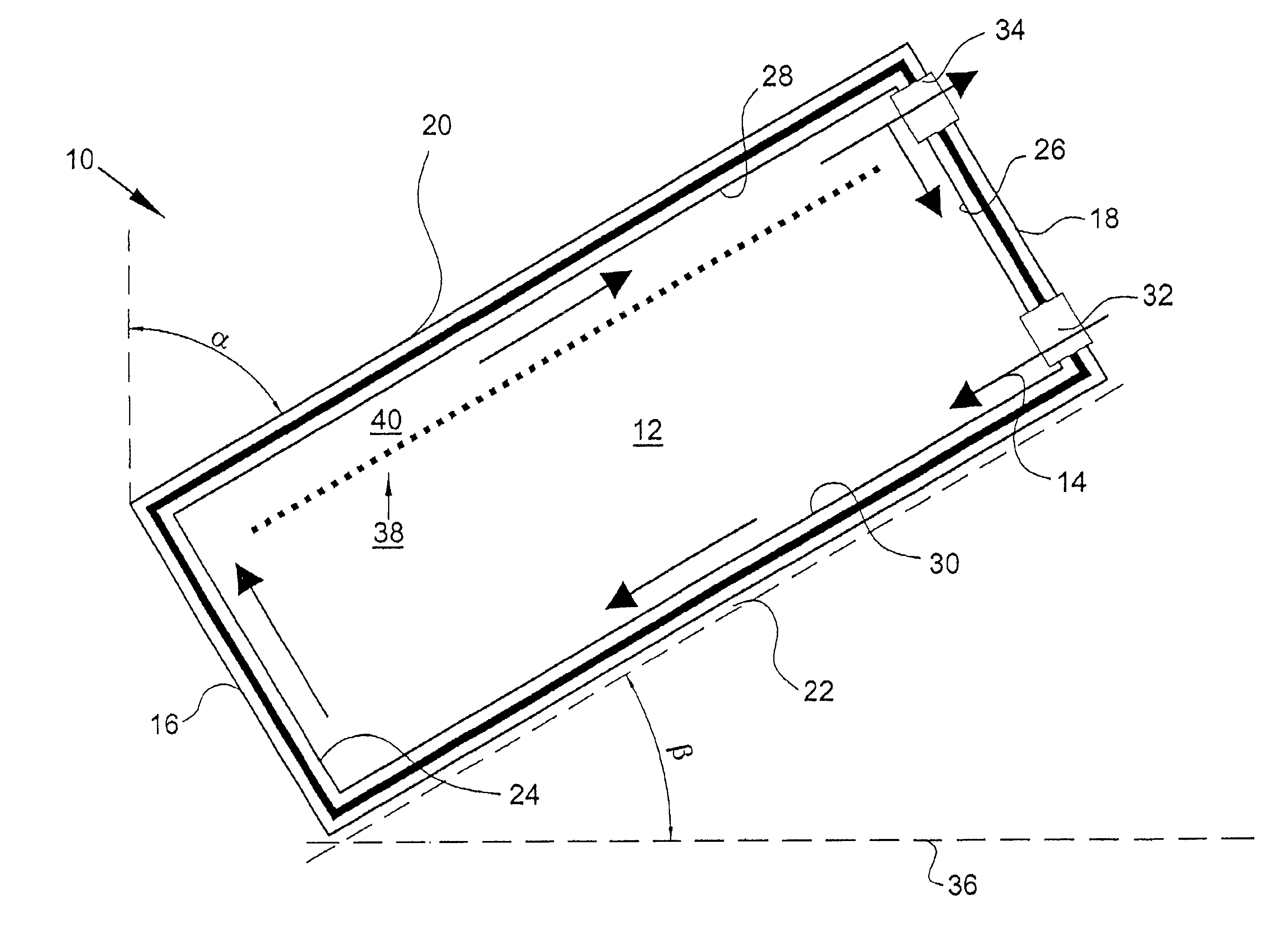
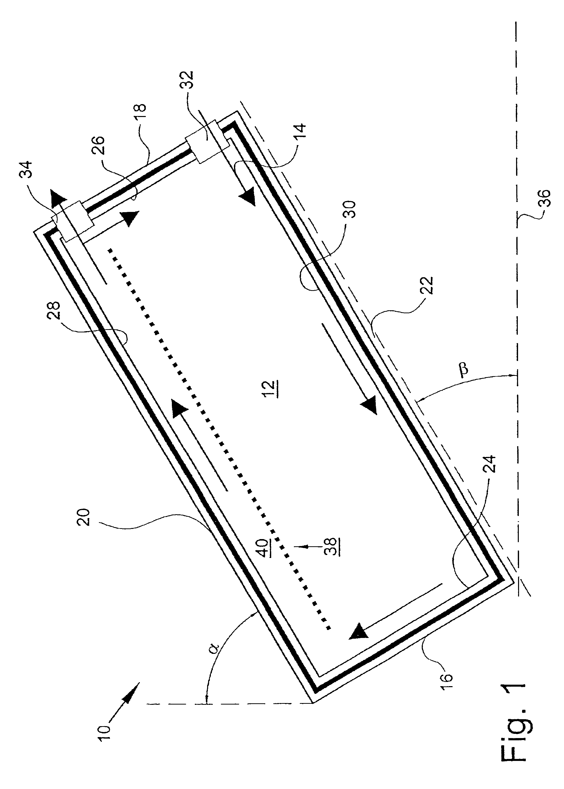
[0040]FIG. 1 a basic sketch of a device for treating and / or coating a surface of an object,

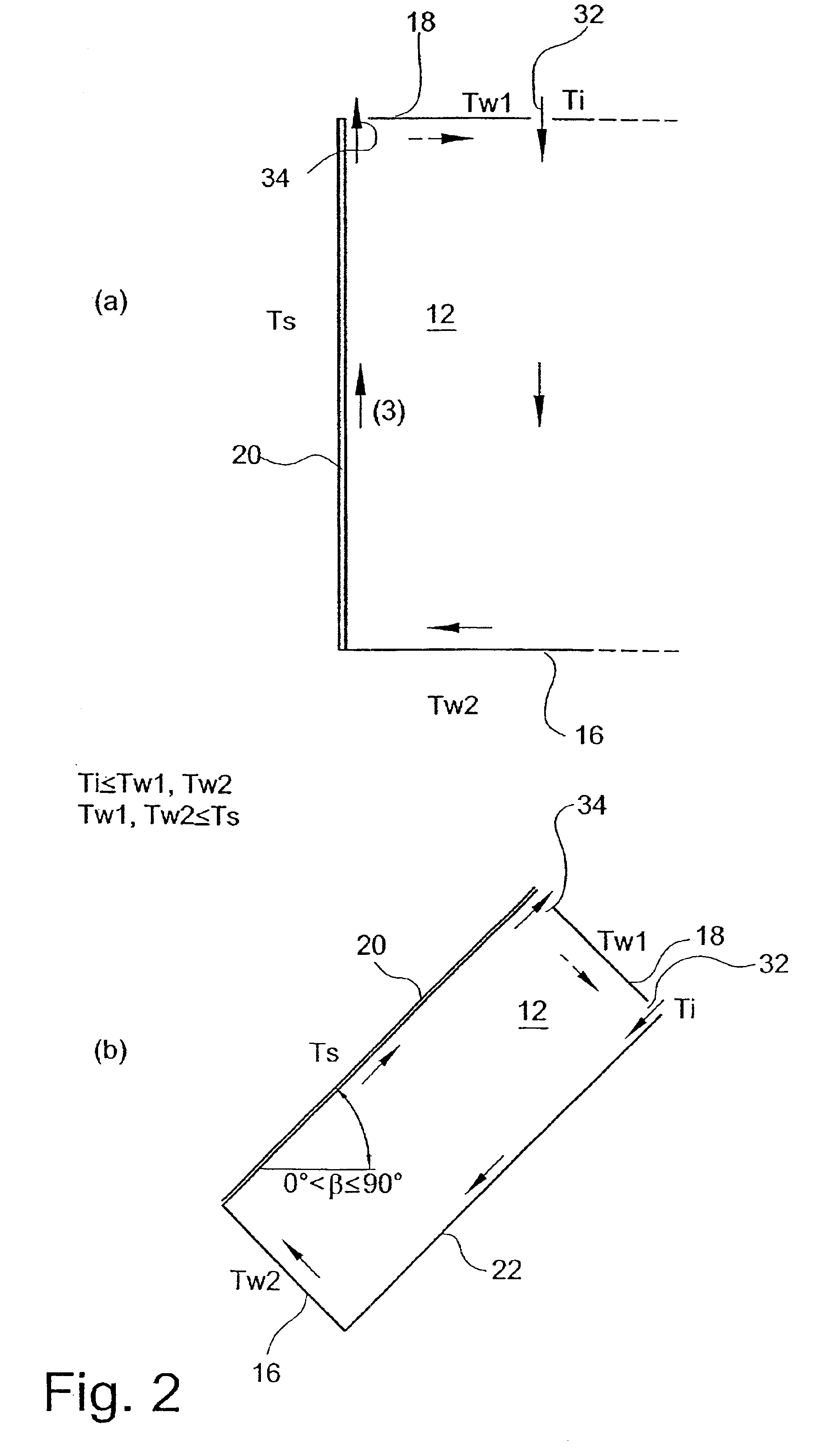
[0041]FIGS. 2a and b the device shown in FIG. 1, in different orientations from vertical,

[0042]FIG. 3 a further basic sketch of a device as shown in FIG. 1,

[0043]FIG. 4 a graphic representation of the rate of deposition on a surface, as a function of its angle of inclination, and

[0044]FIG. 5 a c-Si thin-film solar cell.

DETAILED DESCRIPTION OF THE PREFERRED EMBODIMENTS

[0045]The teaching of the invention with respect to the coating and / or treating of surfa...


PUM

PropertyMeasurementUnit
Temperatureaaaaaaaaaa
Lengthaaaaaaaaaa
Lengthaaaaaaaaaa

Abstract

Method for treating and / or coating a surface of an object, especially for coating a surface of a substrate such as a semiconductor component or solar cell, in which the surface is supplied with a gas that contains particles that will interact and / or react with the surface, forming a coating thereon. The surface of the object is oriented at an angle α from the vertical, and the gas is directed toward the surface such that it flows along the object by force of convection, starting from the base area of the surface of the object.

Description

BACKGROUND OF THE INVENTION[0002]The invention relates to a method for treating and / or coating a surface of an object, especially a surface of a substrate, such as a semiconductor component or solar cell, wherein the surface is supplied with a gas that contains particles that will interact with the surface. The invention further relates to a device for coating and / or treating a surface of an object, such as a substrate, by supplying said substrate with a gas that contains particles for coating and / or treatment, with the device comprising a chamber that is formed by a top panel, a base panel and side panels of the surface to be coated and / or treated, and a longitudinal boundary panel that extends parallel or approximately parallel to said surface; the device further comprises a gas intake and a gas outlet port, and at least one heat source for heating the surface.[0003]In coating substrates and / or surfaces via a CVD process (chemical vapor deposition), various principles of applicati...

Claims


Application Information

Patent Timeline
IPC IPC(8): H01L21/302C23C16/455H01L21/205H01L31/032H01L31/04H01L31/18
CPCC23C16/455H01L31/0322H01L31/18H01L31/1804Y02E10/541Y02E10/547Y02P70/50
Inventor KUNZ, THOMASCAMPE, HILMAR VON
Owner SCHOTT SOLAR GMBH
Learn More