Parallel insulation fault detection system

a technology of parallel insulation and detection system, which is applied in the direction of measurement leads/probes, line-transmission details, instruments, etc., can solve the problems of parallel faults that can develop substantially greater across separations, conductors inside wires being exposed, and parallel faults that may not be detected in time, so as to achieve less effective effect and mitigate the effect of problem

Inactive Publication Date: 2005-04-05
ASTRONICS ADVANCED ELECTRONICS SYST
View PDF4 Cites 43 Cited by
  • Summary
  • Abstract
  • Description
  • Claims
  • Application Information

AI Technical Summary

Benefits of technology

In one useful application the DIF common is connected to the airframe (ground). In this case the tool is responsive to insulation breaks in any connected wire in the aircraft, whether powered or unpowered. The particular advantage of this mode of operation is that it can be used on cable harnesses in-situ without unplugging, turning off, or otherwise disturbing the harness. A disadvantage is that the tool also senses the airframe itself responding much like a metal detector as the probe approaches metal surfaces. The abrupt cutoff of conduction past a certain distance due to the avalanche conduction mechanism, the distance being dependent on the applied voltage, mitigates this problem. Tests on wire bundles several inches above a metal ground plane to simulate typical aircraft cable harnesses have demonstrated that insulation faults along typical cable runs can be effectively found. This mode of operation is clearly less effective where the harness goes through holes in metal struts, for example.

Problems solved by technology

A parallel arcing fault occurs when an undesired electrical arc bridges the gap between two conductors or a conductor and ground.
It is also understood that parallel faults may develop if the separation between said conductors is inadvertently diminished or if the integrity of the insulation is violated as the result of, for example, chafing caused by mechanical vibration.
Conductors inside wires may become exposed as a result of aging cracks or holes in the insulation.
Unfortunately, parallel faults can develop across separations substantially greater than this due to secondary environmental influences.
First, if a voltage surge high enough to span the gap occurs, resulting from an inductive switching transient or perhaps induced by a lightning strike, the localized heating from the momentary arc can carbonize insulating material under the arc, including dust or other contamination on the surface of the wire, and form a high-impedance conduction path.
If the insulation is standard KAPTON (i.e., non fire-resistant), the low-current salt bridge arc will soon involve the KAPTON itself, expand and escalate rapidly into a near explosion of current that often destroys not only the wires involved but also adjacent ones in the wire bundle.
Mechanical chafing of the wire insulation can also lead to parallel arcing.
As the world's fleet of commercial and private aircraft age, particularly now that many aircraft over 20 years old are still flying, the likelihood of such faults occurring increases.
A traditional DC HiPot tester, however, which allows 10 ma of current to flow after breakdown, can itself heat the insulator enough to form a carbon track and damage the insulation.
A conventional HiPot tester can also damage equipment left connected to the harness during testing.
Because access to wiring harnesses is very limited on an operational aircraft, such testing is probably best done during periodic heavy-checks, whereupon panels and floorboards are removed to facilitate access.
Even in this case, however, specific wire bundles may be very long and difficult to access.

Method used


Image

  • Parallel insulation fault detection system
  • Parallel insulation fault detection system
  • Parallel insulation fault detection system

Examples


Embodiment Construction

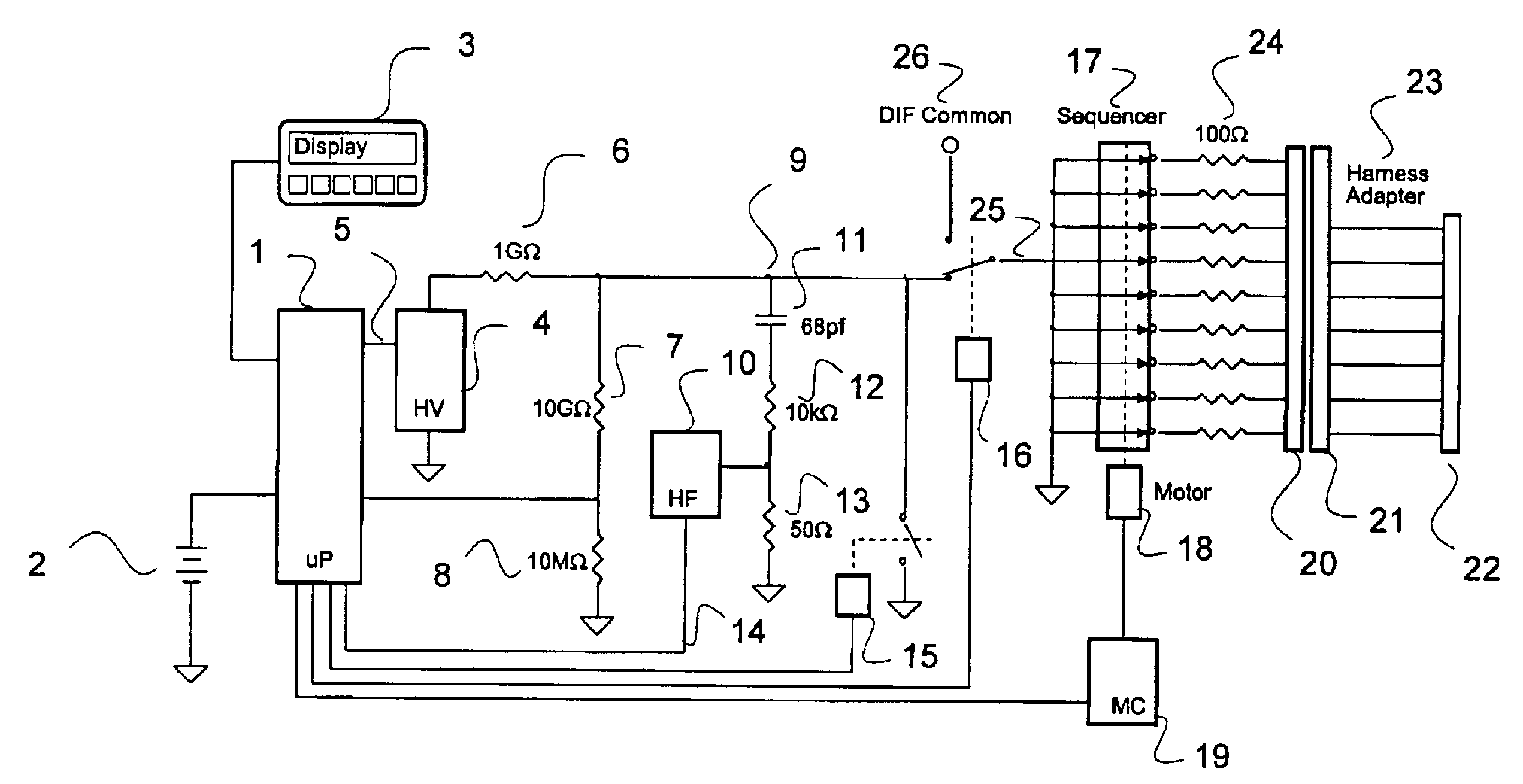
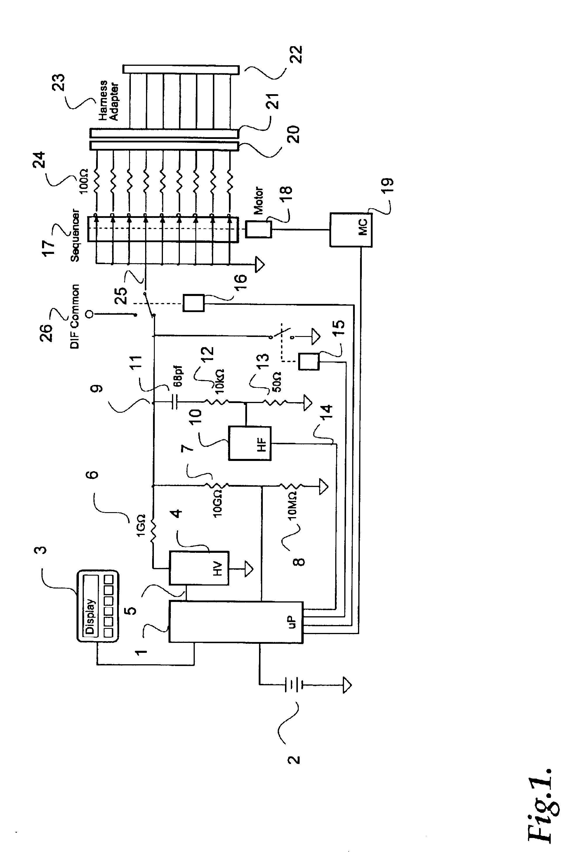
A schematic block diagram of the MED tool is shown in FIG. 1. The microprocessor subsystem 1 represents a control system that includes a microprocessor, interfaces and analog circuits. All of these are conventional implementations available to anyone skilled in the art. The entire system is powered by a rechargeable internal battery 2. The separate keyboard / display unit 3 conveniently connects to the unit with a serial RS232 link. An integral keyboard / display unit could also be used. A low-current high-voltage switching supply 4 produces a DC output voltage that is proportional to a control voltage 5 produced the microprocessor. In this manner, the microprocessor can set the high-voltage as required by the measurement. The maximum voltage should be on the order of 3000V to 6000V depending on the application. A variety of suitable high-voltage supplies are available from EMCO High Voltage Corporation, Sutter Creek, Calif. A high-valued resistor 6 limits the maximum current and makes ...


PUM


Abstract

A device for detecting and locating arcs in a set of wires is discussed. The device comprises a probe for discharging controlled current to an exposed portion of a wire in the set of wires. The probe includes a handleable enclosure and an elongated structure which projects from the enclosure for conducting a gas and for enclosing a needle that has a tip. A suitable gas includes gases that have low electron attachment, such as helium. The device further comprises a control unit for communicating control signals as well as the gas to the probe. The control unit includes a controller, a valve being controllable by the controller and being capable of regulating the flow of the gas, and a high-voltage generator being controllable by the controller to generate a high-voltage signal, which can be communicated to the probe by the control unit.

Description

FIELD OF THE INVENTIONThe present invention relates to the detection of insulation faults in electrical wiring systems that may lead to electrical arcing. More specifically, it relates to a system of diagnostic tools by which insulation faults in wiring systems can be revealed and located before they develop into arcing faults. Although principally directed towards the diagnosis of wiring faults in aircraft wiring systems, these methods and tools apply directly to other fields including residential, industrial and commercial power systems. In this patent the word “fault” is used to refer to both a degradation of the insulation, e.g., an “insulation fault” and a specific failure, e.g., an “arcing fault.”BACKGROUND OF THE INVENTIONA parallel arcing fault occurs when an undesired electrical arc bridges the gap between two conductors or a conductor and ground. Since the dielectric strength of air is known to be approximately 31 kV / cm, it is generally understood that exposed conductors i...

Claims


Application Information

Patent Timeline
Patent Type & Authority Patents(United States)
IPC IPC(8): G01R15/16G01R1/067G01R15/14G01R1/07G01R31/11G01R31/08
CPCG01R1/07G01R31/11G01R15/16
Inventor BLADES, FREDERICK K.
Owner ASTRONICS ADVANCED ELECTRONICS SYST
Why Eureka
Try Eureka