Micro-electro-mechanical RF switch

Inactive Publication Date: 2005-04-05
IBM CORP
View PDF3 Cites 18 Cited by
  • Summary
  • Abstract
  • Description
  • Claims
  • Application Information

AI Technical Summary

Benefits of technology

Therefore, it is an object of the present invention to provide a single-pole, multi-throw MEMS RF switch t

Problems solved by technology

However, these have high power consumption rates, high losses (typically 1 dB insertion loss at 2 GHz), and are non-linear devices.
Decoupling is never 100% and there are always some losses to the RF signal power either by adding resistive losses or by direct leakage.
Another source of losses is capacitive coupling of actuators to the RF signal (especially

Method used


Image

  • Micro-electro-mechanical RF switch
  • Micro-electro-mechanical RF switch
  • Micro-electro-mechanical RF switch

Examples


Example

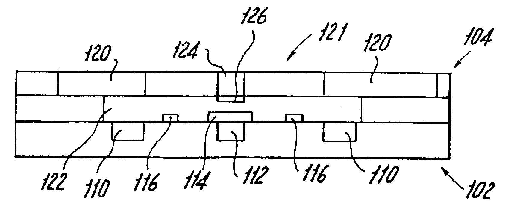
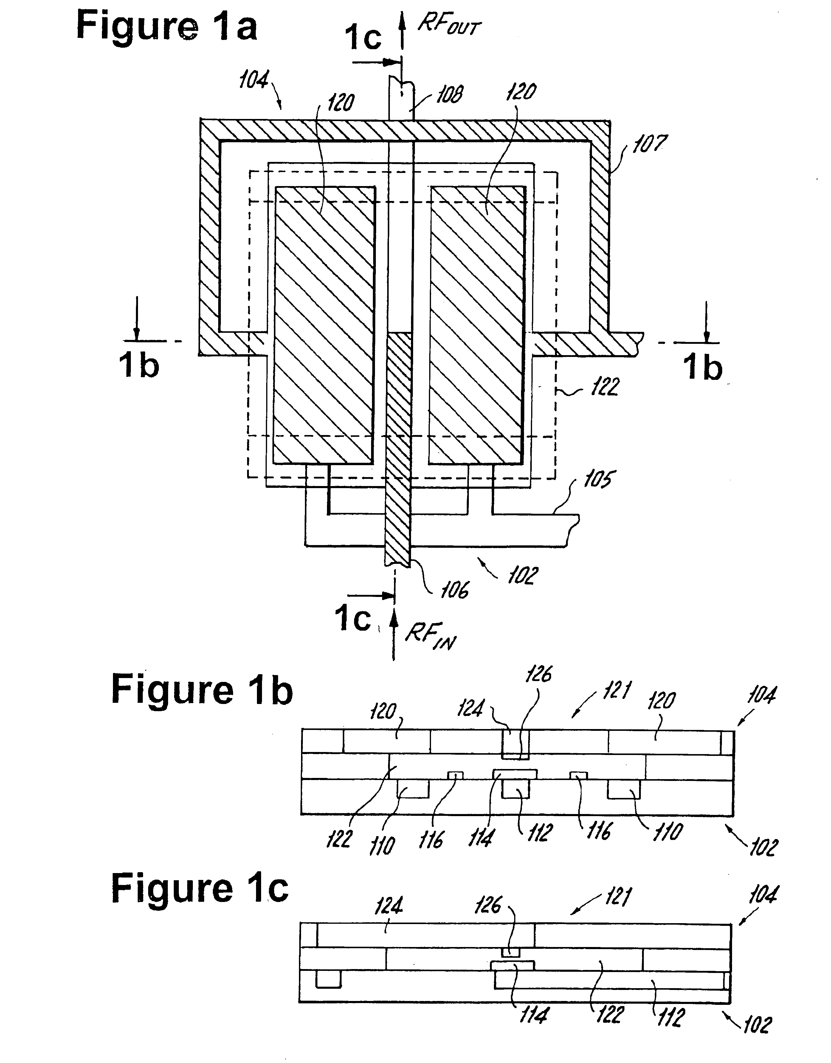
Referring now to FIGS. 1a, 1b, and 1c there is illustrated a single-contact MEMS, generally referred to by reference numeral 100. The single contact MEMS 100 is electrostatically activated as will be described below. Although the MEMS switch 100 illustrated in FIGS. 1a, 1b, and 1c is a single-pole, single-throw switch, such is given by way of example only and not to limit the scope or spirit of the present invention. Those skilled in the art will realize that multiple pole and / or multiple-throw configurations are also possible, as described below.

Referring to FIG. 1a, a top schematic view of the MEMS 100 is shown in which a first level portion 102 of the switch 100 is shown with solid areas while a second level portion 104 is shown with hatched areas. In the preferred implementation of the switch 100, the first level portion 102 is a lower level, while the second level portion 104 is an upper level portion. However, those skilled in the art will appreciate that the switch 100 can be...


PUM


Abstract

A microelectromechanical switch including: at least one pair of actuator electrodes; at least one input electrode and at least one output electrode for input and output, respectively, of a radio frequency signal; and a beam movable by an attraction between the at least one pair of actuator electrodes, the movable beam having at least a portion electrically connected to the at least one input electrode and to the at least one output electrode when moved by the attraction between the at least one pair of actuator electrodes to make an electrical connection between the at least one input and output electrodes; wherein the at least one pair of actuator electrodes are electrically isolated from each of the at least one input and output electrodes. The microelectromechanical switch can be configured in single or multiple-poles and/or single or multiple throws.

Description

BACKGROUND OF THE INVENTION1. Field of the InventionThe present invention relates generally to RF switches, and more particularly, to single-pole, multi-throw (micro-electro-mechanical) MEMS RF switches.2. Prior ArtMEMS switches are called as such because they use electrostatic actuation to create movement of a beam or membrane that results in an- ohmic contact (i.e. an RF signal is allowed to pass-through) or by a change in capacitance by which the flow of signal is interrupted and typically grounded.In a wireless transceiver, pin diodes or GaAs MESFET's are used as switches. However, these have high power consumption rates, high losses (typically 1 dB insertion loss at 2 GHz), and are non-linear devices. MEMS switches on the other hand, have demonstrated insertion loss of less than 0.5 dB, are highly linear, and have very low power consumption since they use a DC voltage for electrostatic actuation. If the actuators are coupled to the RF signal in a series switch, then the DC bias...

Claims


Application Information

Patent Timeline
IPC IPC(8): H01H59/00
CPCH01H59/0009H01H2001/0078
Inventor ANDRICACOS, PANAYOTIS CONSTANTINOUBUCHWALTER, L. PAIVIKKIDELIGIANNI, HARIKLIAGROVES, ROBERT A.JAHNES, CHRISTOPHERLUND, JENNIFER L.MEIXNER, MICHAELSEEGER, DAVID EARLESULLIVAN, TIMOTHY D.WANG, PING-CHUAN
Owner IBM CORP
Why Eureka
Try Eureka