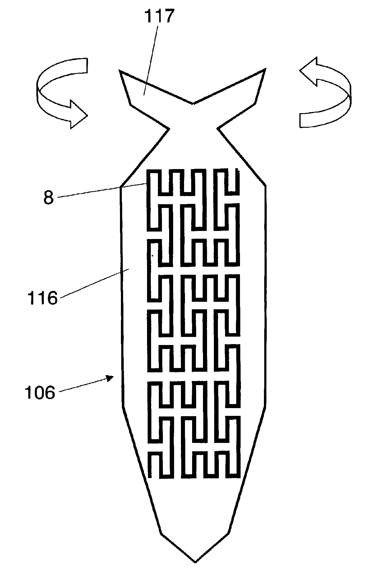
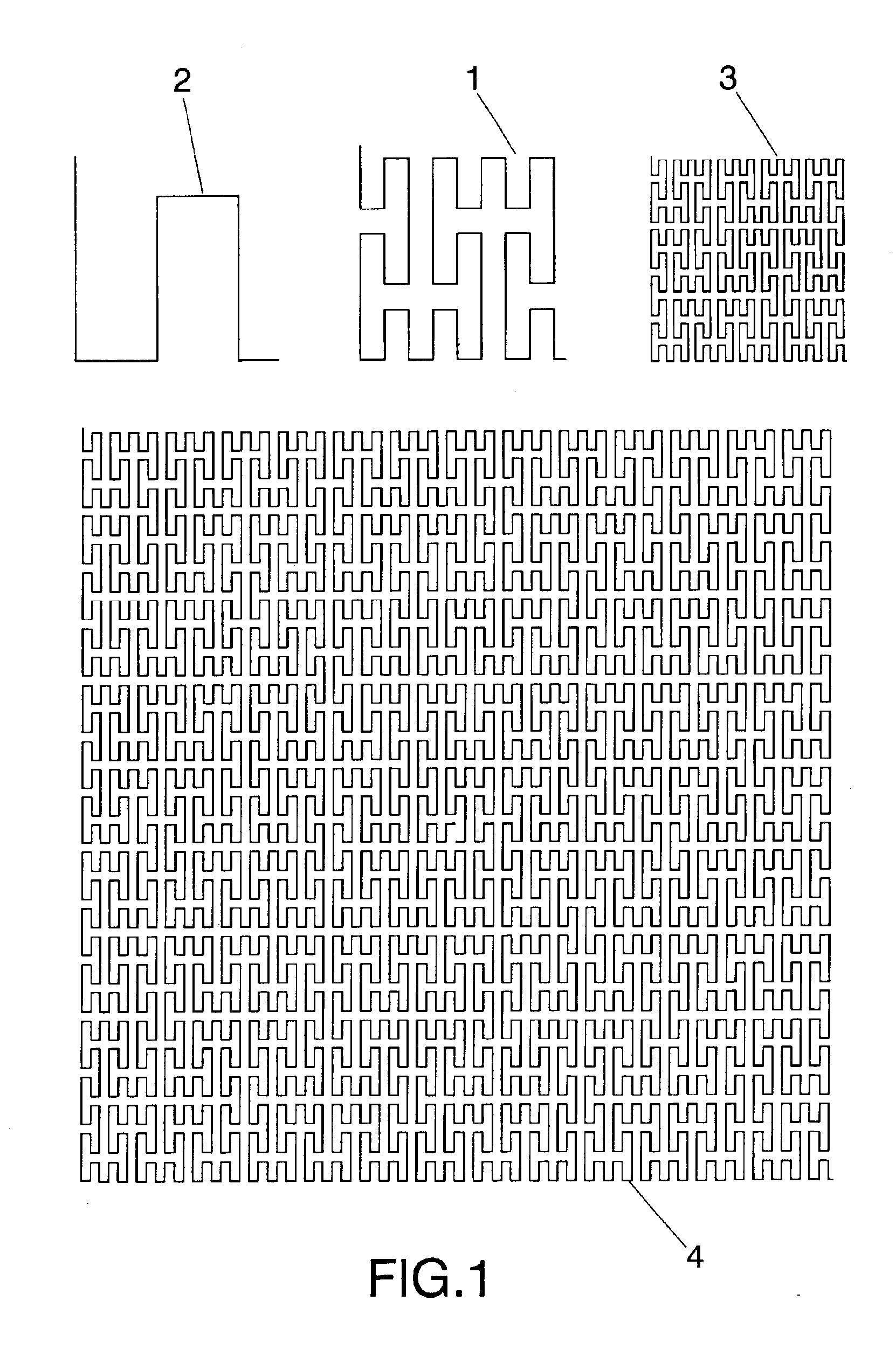
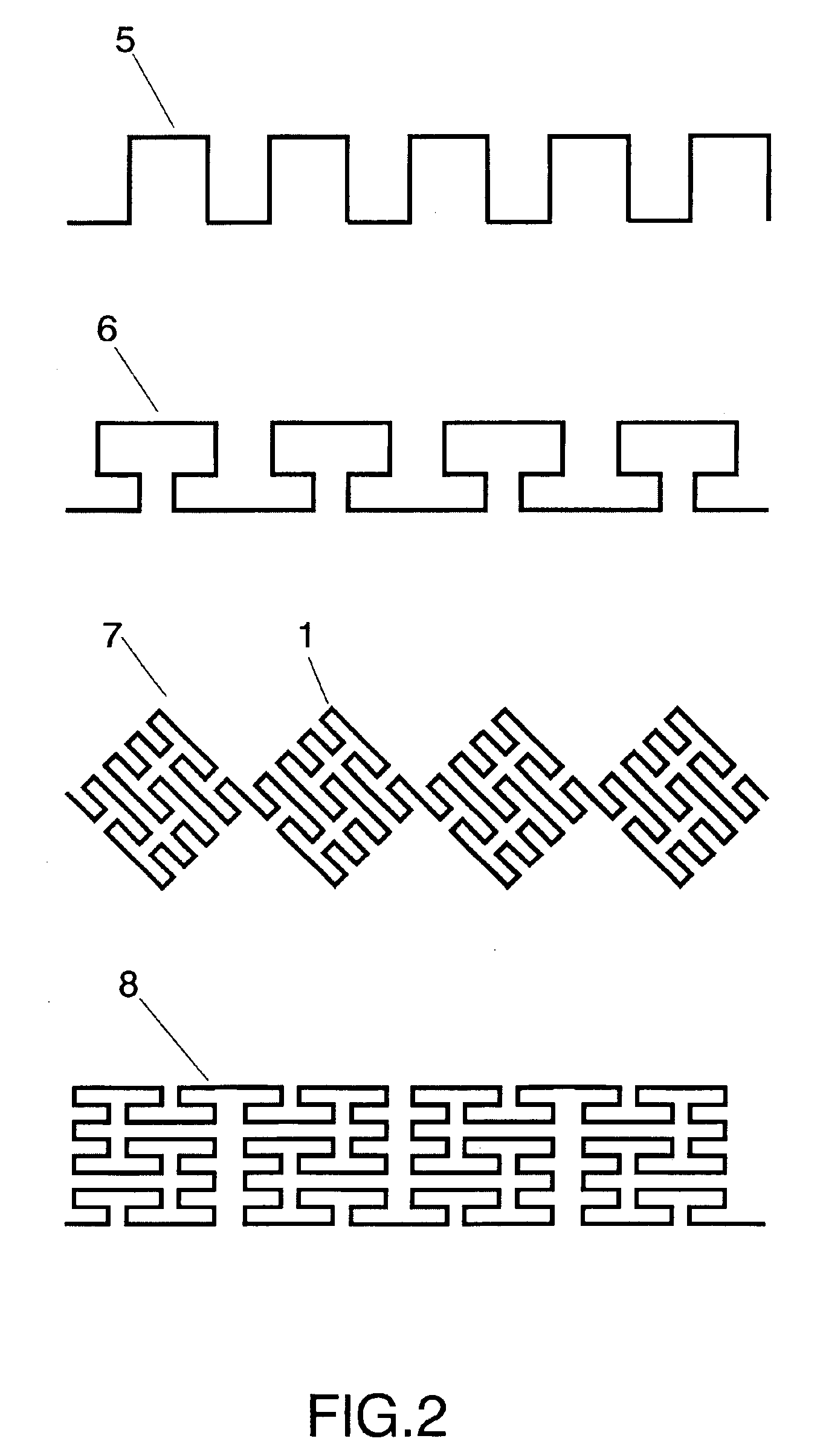
It is to be stressed that, beyond the reflective response of the new dispersers presented for radar chaff, the benefit resulting from using these new geometries with regard to the state of the art is the aerodynamic profile thereof. Being highly complicated and irregular forms, the friction with the air is improved by improving the time of suspension with regard to the state of the art. This new effect is directly related with the new geometry presented and bears no relation with the electromagnetic behaviour of the
disperser.
Another characteristic of the space-filling dispersers is their
frequency response. Their complex geometry provides a spectrally richer signature when compared with rectilinear dispersers known in the state of the art. Non-
harmonic frequency responses are obtained with pass-bands and stop-bands distributed unequally, which is of great utility when the intention is to improve the
clutter effect of the chaff cloud over a wider margin of radar frequencies.
The space-filling properties of SFC dispersers not only introduce an
advantage in terms of reflected radar
signal response, but also in terms of the aerodynamic profile of said dispersers. It is known that a surface offers greater resistance to air than a line or a one-dimensional form. Therefore, giving form to the dispersers with SFC with a dimension greater than unity (D>1), increases resistance to the air and improves the time of suspension. In the case of SFC with D approaching 2 (like for example the designs in FIG. 1 and FIG. 3), the surface-like behaviour is maximized, and for this reason a
disperser is obtained which has a reflection response similar to a linear form, but which is smaller and at the same time is characterised in that it has a resistance to air proper to that of a surface. Although the improvement in time of suspension and resistance to advance are directly related with the geometry presented in the present invention, this effect is totally different to the electromagnetic one and it cannot be deduced or predicted from the electromagnetic properties of the dispersers.
In like manner to space-filling forms, multilevel structures provide both a reduction in the sizes of dispersers and an enhancement of their
frequency response. The dispersers which are at least partially formed by multilevel structures will be smaller than those described in the state of the art, and they provided a better multiband response. Multilevel structures can resonate in a non-
harmonic way, and can even cover simultaneously and with the same
relative bandwidth at least a portion of numerous bands: HF, VHF, UHF, L, S, C, X, Ku, K, Ka and mm.
In like manner to space-filling forms, multilevel structures for radar chaff also provide a better aerodynamic profile with respect to chaff of the state of the art. Multilevel structures are characterised in having multiple holes between polygons, an irregular perimeter (for example an SFC perimeter) or a combination of both characteristics. When the dispersers are constructed with only one conducting material, this conducting material being constructed in multilevel structure form, said holes and the perimeter of both characteristics introduce turbulence in the air which changes the resistance to the advance of the
disperser when compared with conventional dispersers used in non-multilevel structures. Also, the multiple holes on the interior of the multilevel structure introduce a reduction in the total of the conducting surface of the disperser, which means the disperser is lighter than conventional dispersers of the same sizes and enclosing the same
solid area. Again this effect is related with the particular geometry expounded in the present invention, but it has no relation and cannot be predicted from the
electromagnetic response or the behaviour of said structures.
The main advantages for configuring the form of the chaff dispersers according to the present invention are (although not limited by):1) The dispersers are small, consequently more dispersers can be encapsulated in a same
cartridge,
rocket or
launch vehicle. This means that the same device will provide a larger RCS with respect to chaff of the state of the art.2) The dispersers are also lighter, therefore they can remain more time floating in the air than the conventional chaff.3) Due to the smaller size of the chaff dispersers, the launching devices (cartridges, rockets, etc.) can be smaller with regard to chaff systems in the state of the art providing the same RCS.4) Due to the lighter weight of the chaff dispersers, the launching devices can
shoot the packages of chaff farther from the launching devices and locations.5)
Chaff constituted by multilevel and space-filling structures provide larger RCS at longer wavelengths than conventional chaff dispersers of the same size.6) The dispersers with long wavelengths can be configured and printed on light
dielectric supports having a non-aerodynamic form and opposing a greater resistance to the air and thereby having a longer time of suspension.7) In a
package of the state of the art of the same size, a greater number of disperser sizes can be included, increasing the spectral margin covered by the chaff cloud.8) The dispersers provide a better
frequency response with regard to dispersers of the state of the art, which signifies:a) A simple disperser can be designed to cover all frequency bands instead of using a disperser element for each band.b) A simple disperser can provide a larger bandwidth for each radar band due to its non-
harmonic electromagnetic response.


