Network device with a distributed switch fabric timing system

a network device and fabric timing technology, applied in data switching networks, generating/distributing signals, multiplex communication, etc., to achieve the effect of reducing the cost of a minimally configured network devi

Inactive Publication Date: 2005-04-05
CIENA
View PDF31 Cites 103 Cited by
  • Summary
  • Abstract
  • Description
  • Claims
  • Application Information

AI Technical Summary

Benefits of technology

The present invention provides a central switch fabric timing subsystem and distributed switch fabric timing subsystems. Distributed switch fabric subsystems reduce the cost of a minimally configured network device by providing a network device that separates the switch fabric functionality into a central switch fabric provided with a minimally configured network device and distributed switch fabrics that may be added to the network device as services are needed. Locating certain switch fabric components onto each forwarding card or other cards reduces the cost of a minimally configured network device. Additional costs may be achieved by providing 1:N redundancy for the distributed switch fabric subsystems as opposed to 1:1 redundancy.

Problems solved by technology

When the signal indicates that the status of the first timing reference signal is invalid, the control logic circuit may further cause the selector circuit to send the second timing reference signal to the phase locked loop circuit.
When the signal indicates that the status of the second timing reference signal is invalid, the control logic circuit may further cause the selector circuit to send the first timing reference signal to the phase locked loop circuit.

Method used


Image

  • Network device with a distributed switch fabric timing system
  • Network device with a distributed switch fabric timing system
  • Network device with a distributed switch fabric timing system

Examples


Embodiment Construction

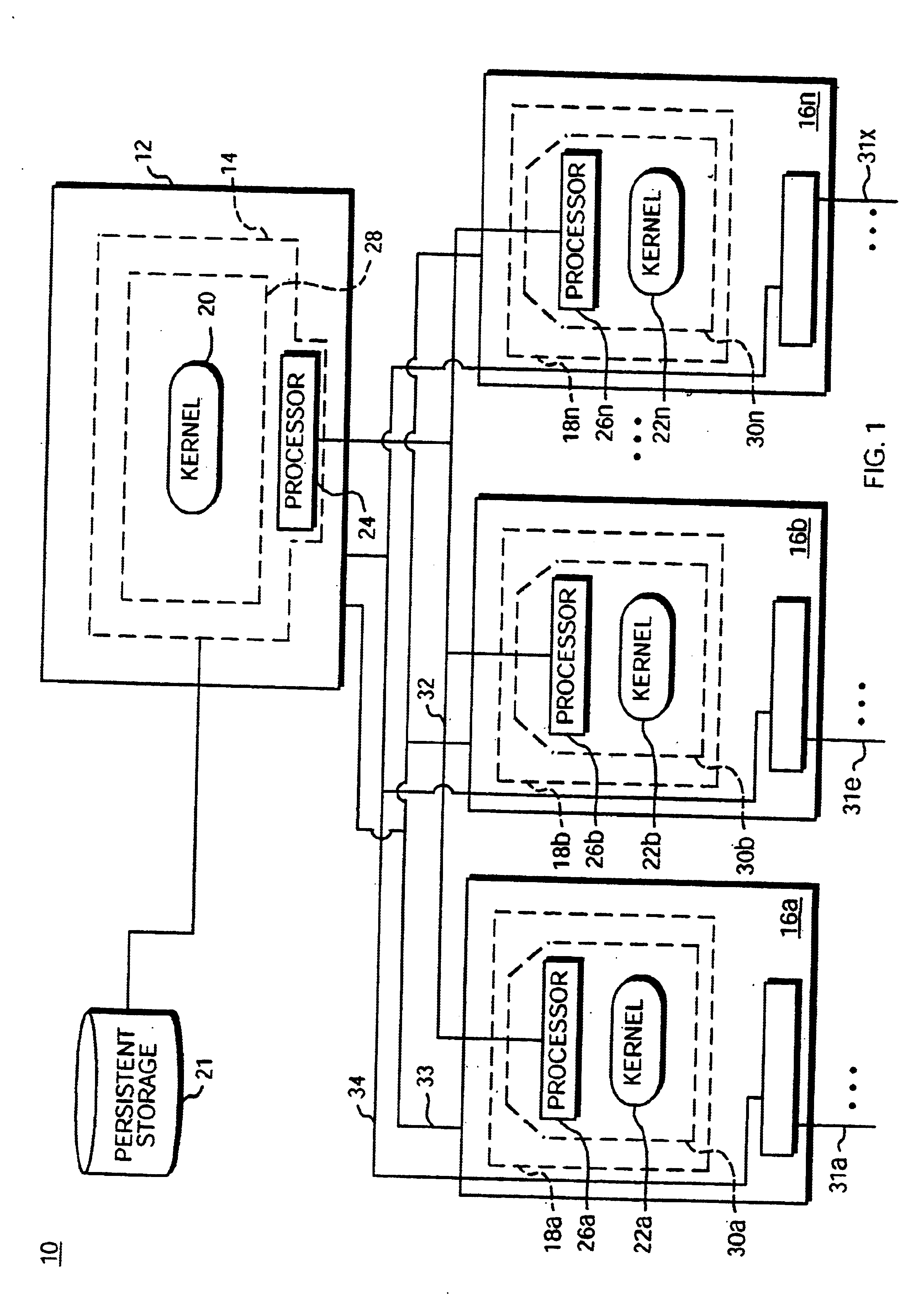
A modular software architecture solves some of the more common scenarios seen in existing architectures when software is upgraded or new features are deployed. Software modularity involves functionally dividing a software system into individual modules or processes, which are then designed and implemented independently. Inter-process communication (IPC) between the modules is carried out through message passing in accordance with well-defined application programming interfaces (APIs). A protected memory feature also helps enforce the separation of modules. Modules are compiled and linked as separate programs, and each program runs in its own protected memory space. In addition, each program is addressed with an abstract communication handle, or logical name. The logical name is location-independent; it can live on any card in the system. The logical name is resolved to a physical card / process during communication. If, for example, a backup process takes over for a failed primary pro...


PUM


Abstract

The present invention provides a central switch fabric timing subsystem and distributed switch fabric timing subsystems. Distributed switch fabric subsystems reduce the cost of a minimally configured network device by providing a network device with a distributed switch fabric. Such a network device locates a portion of the switch fabric functionality on each forwarding card allowing the minimal network device configuration to include less than the entire switch fabric functionality. The cost of the minimal configuration is, therefore, reduced allowing network service providers to more quickly recover the initial cost of the network device. As new services are requested, additional functionality, including both forwarding cards and universal port cards may be added to the network device to handle the new requests, and the fees for the new services may be applied to the cost of the additional functionality. Consequently, the cost of the network device more closely tracks the service fees received by network providers.

Description

BACKGROUNDThe major function of a telecommunications (“telco”) network device such as a switch, router or hybrid switch / router is to transfer network data or packets between various physical interfaces or ports on the network device. The ports are connected to external network attachments, for example, optical fibers, coaxial cables and twisted pair cables. Typically, a network device includes multiple forwarding cards (i.e., printed circuit boards or modules) coupled with the external network attachments through the physical interfaces. Network packets are transferred between forwarding cards through a switch fabric.In older network devices, the switch fabric functionality was spread out or distributed amongst the forwarding cards—that is, the network device included a totally distributed switch fabric. As the size and complexity of network devices has increased, the number of signals / etches required to connect distributed switch fabrics has significantly grown. To avoid having to ...

Claims


Application Information

Patent Timeline
Patent Type & Authority Patents(United States)
IPC IPC(8): G06F1/14H04L29/06H04L7/00H04J3/06H04L12/24H04L12/56
CPCG06F1/14H04J3/0685H04L7/0008H04L29/06H04L69/18H04L41/085H04L41/22H04L45/50H04L41/0803H04L9/40
Inventor BELL, COLINBRANSCOMB, BRIAN
Owner CIENA
Why Eureka
Try Eureka