
Downhole sorption cooling and heating in wireline logging and monitoring while drilling

a technology of wireline logging and monitoring, applied in the field of downhole tools, can solve the problems of thermally exposed electronic components that are often heated by electronic components, the temperature of the formation itself exceeding the maximum temperature capability of components, and the life expectancy of thermally exposed electronic components is reduced, so as to facilitate the transfer of heat and effectively cool electronic components

Inactive Publication Date: 2005-04-12
BAKER HUGHES INC
View PDF20 Cites 43 Cited by
  • Summary
  • Abstract
  • Description
  • Claims
  • Application Information

AI Technical Summary

Benefits of technology

It is an object of the current invention to provide a rugged yet reliable system for effectively cooling the electronic components that is suitable for use in a well, and preferably, that is capable of being used in a downhole assembly of a drill string or wireline. This and other objects is accomplished in a sorption cooling system in which an electronic component or sensor is juxtaposed with one or more sorbent coolers that facilitate the transfer of heat from the component to the wellbore.

Problems solved by technology

Unfortunately, many of these electronic components generate heat.
Moreover, even if the electronic component itself does not generate heat, the temperature of the formation itself typically exceeds the maximum temperature capability of the components.
Overheating frequently results in failure or reduced life expectancy for thermally exposed electronic components.
Unfortunately, cooling is made difficult by the fact that the temperature of the formation surrounding deep wells, especially geothermal wells, is typically relatively high, and may exceed 200° C.
Such approaches are not suitable for use in drill strings since the size of such configurations makes them difficult to package into a downhole assembly.
This approach, however, does not ensure that there will be adequate contact between the components to ensure efficient heat transfer, nor is the electronic component protected from the shock and vibration that it would experience in a drilling application.
Thus, one of the prominent design problems encountered in downhole logging tools is associated with overcoming the extreme temperatures encountered in the downhole environment.
Various schemes have been attempted to resolve the temperature differential problem to keep the tool temperature below the maximum electronic operating temperature, but none of the known techniques have proven satisfactory.
Downhole tools are exposed to tremendous thermal strain.
Thus, the thermal load on a non-insulated downhole tool's electronic system is enormous and can lead to electronic failure.
Electronic failure is time consuming and expensive.
Such attempts at thermal load reduction, while partially successful, have proven problematic in part because of heat conducted from outside the electronics chamber and into the electronics flask via the feed-through wires connected to the electronics.
Moreover, heat generated by the electronics trapped inside of the flask also raises the ambient operating temperature.
Electronic container flasks, unfortunately, take as long to cool down as they take to heat up.
Thus, once the internal flask temperature exceeds the critical temperature for the electronics, it requires many hours to cool down before an electronics flask can be used again safely.
As discussed above, electronic cooling via thermoelectric and compressor cooling systems has been considered, however, neither have proven to be viable solutions.
Thermoelectric coolers require too much external power for the small amount of cooling capacity that they provide.
Moreover, few if any of the thermoelectric coolers are capable of operating at downhole temperatures.
Compressor-based cooling systems also require considerable power for the limited amount of cooling capacity they provide.
Also, most compressors seals cannot operate at the high temperatures experienced downhole because they are prone to fail under the thermal strain.
Another problem encountered during downhole operations is cooling and associated depressurization of hydrocarbon samples taken into a downhole tool.

Method used


Image

  • Downhole sorption cooling and heating in wireline logging and monitoring while drilling
  • Downhole sorption cooling and heating in wireline logging and monitoring while drilling
  • Downhole sorption cooling and heating in wireline logging and monitoring while drilling

Examples


Embodiment Construction

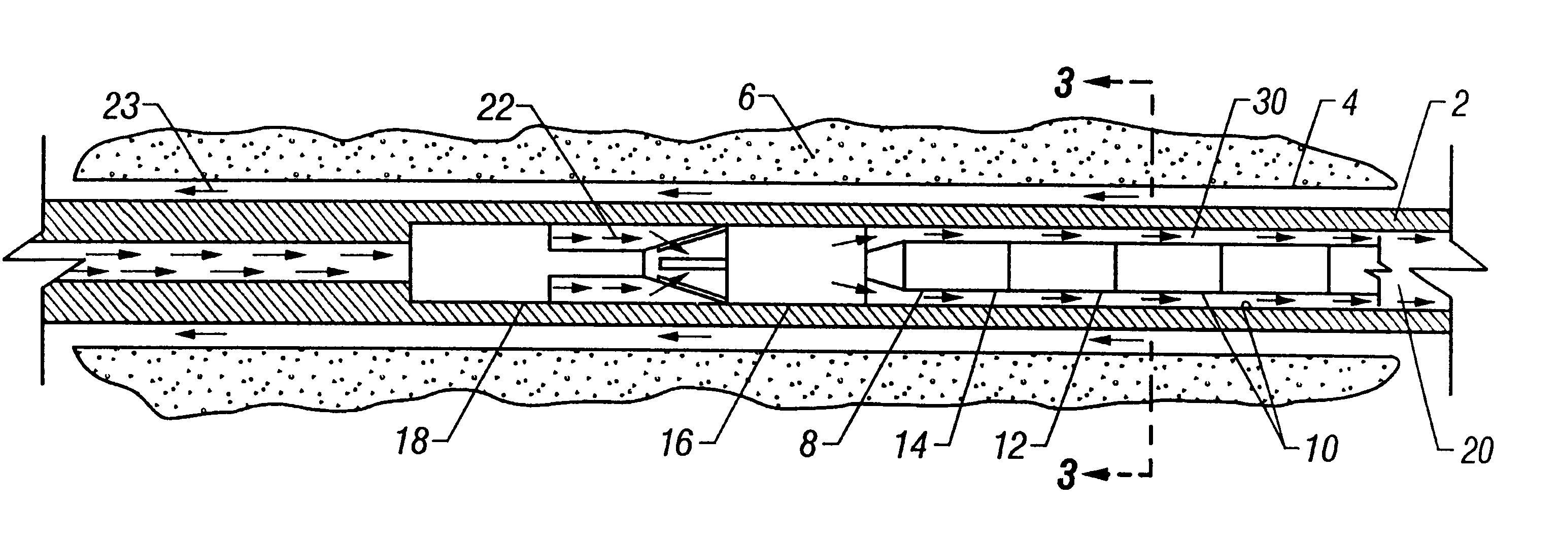
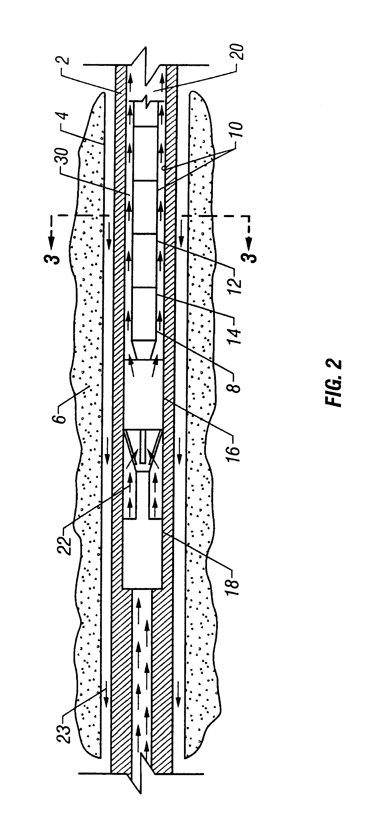
The present invention provides a structure and method for a downhole tool component cooling system. The downhole tool component cooling system of the present invention does not require an external power source. The cooling system of the present invention utilizes the potential energy of sorption as the source of energy for pumping heat from a first region of the tool, housing the tool component which is to be cooled, to a hotter region in the downhole tool. The cooling region of the tool, adjacent to the component to be cooled, contains a solid source of liquid (such as water). This solid water source can be a low-temperature hydrate, desiccant, or sorbent from which water (or some other liquid) vapor is generated when heated. For example, when a portion of a hydrate releases water vapor, the remaining portion of the hydrate is cooled, and this in turn cools the adjacent component, thereby keeping the component within a safe operating temperature. Thus, the present invention provide...


PUM


Abstract

A cooling system in which an electronic or other component is cooled by using one or more solid sources of liquid vapor in conjunction with one or more high-temperature vapor sorbents or desiccants that effectively transfer heat from the component to the fluid in the wellbore. The latent heats associated with phase changes and dehydration of a hydrate can provide substantial cooling capacity per unit volume of hydrate, which is particularly important in those applications where space is limited. According to the present invention, a sorption cooling and heating system is provided for use in a well, such as downhole tool which is in a drill string through which a drilling fluid flows, or in a downhole tool, which is on a wireline. Electronics, sensors, or clocks adjacent to a hydrate are not only kept cool by the heat sinking effect of hydrate phase changes and evaporation of water that is released but, during phase changes, they are being kept at a constant temperature for extended periods of time, which further improves their stability. Furthermore, such a system can also be used to heat a sample chamber or other component by placing it adjacent to the high-temperature sorbent or desiccant that heats up as it adsorbs the water vapor that was released by a low-temperature hydrate or desiccant during dehydration.

Description

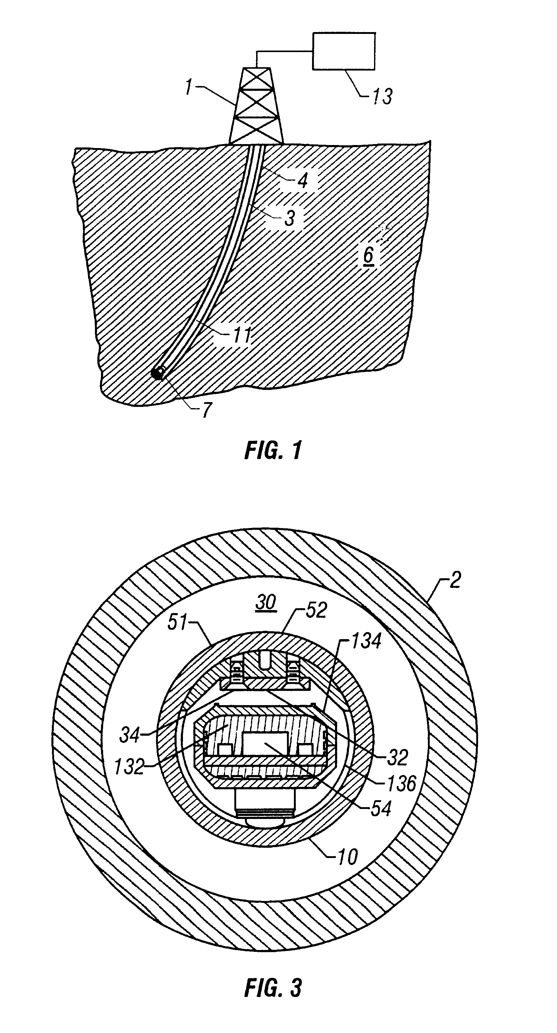
BACKGROUND OF THE INVENTION1. Field of the InventionThis present invention relates to a downhole tool for wireline or monitoring while drilling applications, and in particular relates to a method and apparatus for sorption cooling of sensors and electronics and heating of chambered samples deployed in a downhole tool suspended from a wireline or a drill string.2. Summary of Related ArtIn underground drilling applications, such as oil and gas or geothermal drilling, a bore hole is drilled through a formation deep in the earth. Such bore holes are drilled or formed by a drill bit connected to the end of a series of sections of drill pipe, so as to form an assembly commonly referred to as a “drill string.” The drill string extends from the surface to the bottom of the bore hole. As the drill bit rotates, it advances into the earth, thereby forming the bore hole. In order to lubricate the drill bit and flush cuttings from its path as it advances, a high pressure fluid, referred to as “d...

Claims


Application Information

Patent Timeline
Patent Type & Authority Patents(United States)
IPC IPC(8): E21B47/01E21B47/00E21B36/00E21B49/08
CPCE21B36/003E21B49/08E21B47/011E21B47/017E21B47/0175
Inventor DIFOGGIO, ROCCO
Owner BAKER HUGHES INC
Learn More