
In-well monitoring and flow control system

a flow control and well technology, applied in the field of well monitoring and flow control systems, can solve the problem that the resistance of the armoured cable may be too high to provide a satisfactory return path, and achieve the effect of too high resistance of the armoured cabl

Inactive Publication Date: 2005-04-12
EXPRO NORTH SEA
View PDF10 Cites 6 Cited by
  • Summary
  • Abstract
  • Description
  • Claims
  • Application Information

AI Technical Summary

Benefits of technology

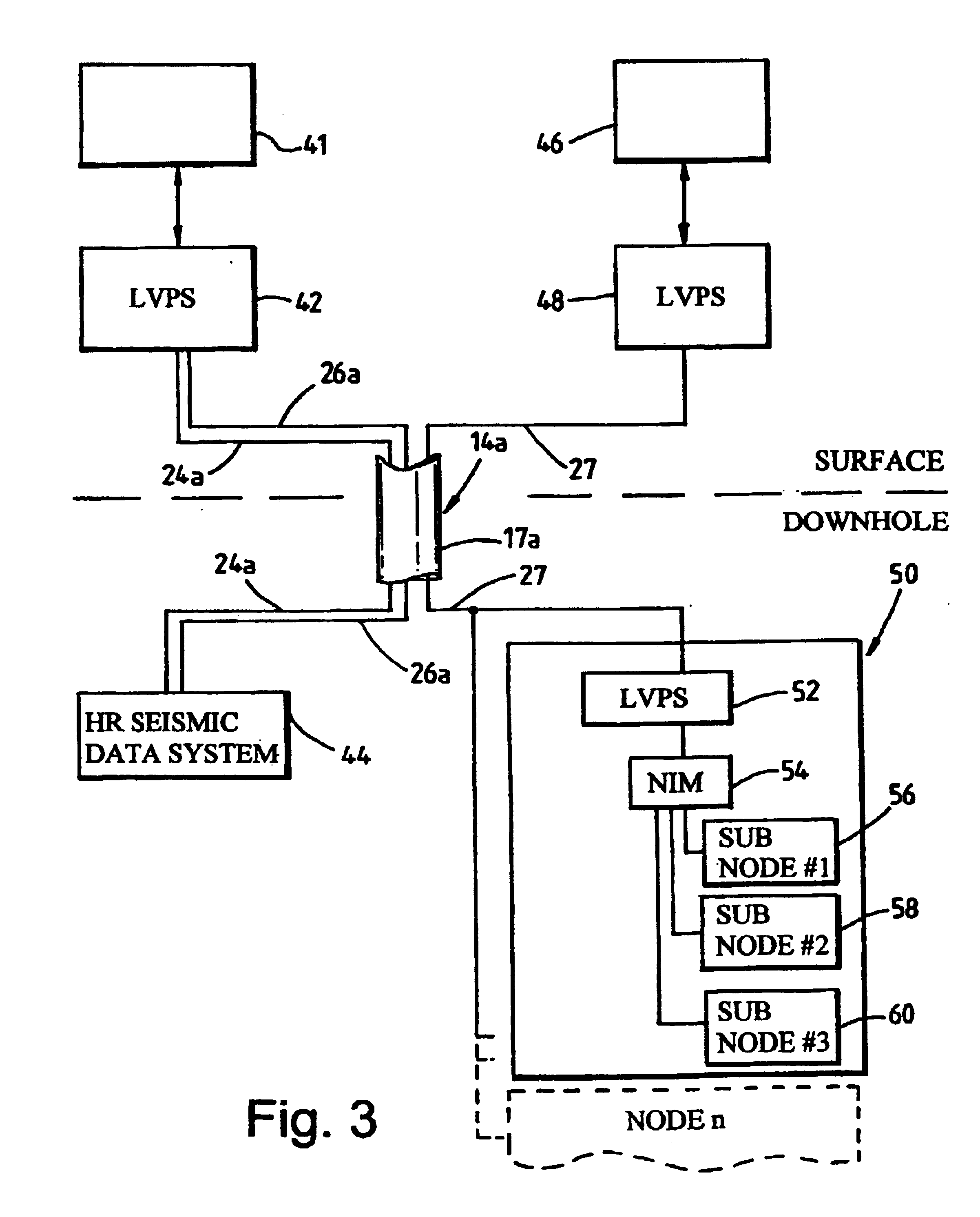
This solution provides a number of advantages over the aforementioned prior art arrangements. Firstly, the maximum high power which can be used is not limited to 400 volts; and the system can be used for up to 255 downhole devices. A further advantage is that voltage can be varied at surface to suit the downhole hardware and the system can be powered up during deployment because the low voltage line can be used to continuously monitor what is happening downhole. A yet further advantage is that the position of a downhole component such as a valve can be monitored and high voltage power supplied to make further movements. The cable sheathing is used as the earth return in shallower wells providing the advantage that a separate earth is not needed for shallower wells. A shallow well may be considered as one less than 4,000 feet. However, for deeper wells, in excess of 4,000 feet, the resistance of the armoured cable may be too high to provide a satisfactory return path and, in such a case, a cable with three cores is used; one for high voltage power, one for low voltage and one for an earth return.

Problems solved by technology

However, for deeper wells, in excess of 4,000 feet, the resistance of the armoured cable may be too high to provide a satisfactory return path and, in such a case, a cable with three cores is used; one for high voltage power, one for low voltage and one for an earth return.

Method used


Image

  • In-well monitoring and flow control system
  • In-well monitoring and flow control system
  • In-well monitoring and flow control system

Examples


Embodiment Construction

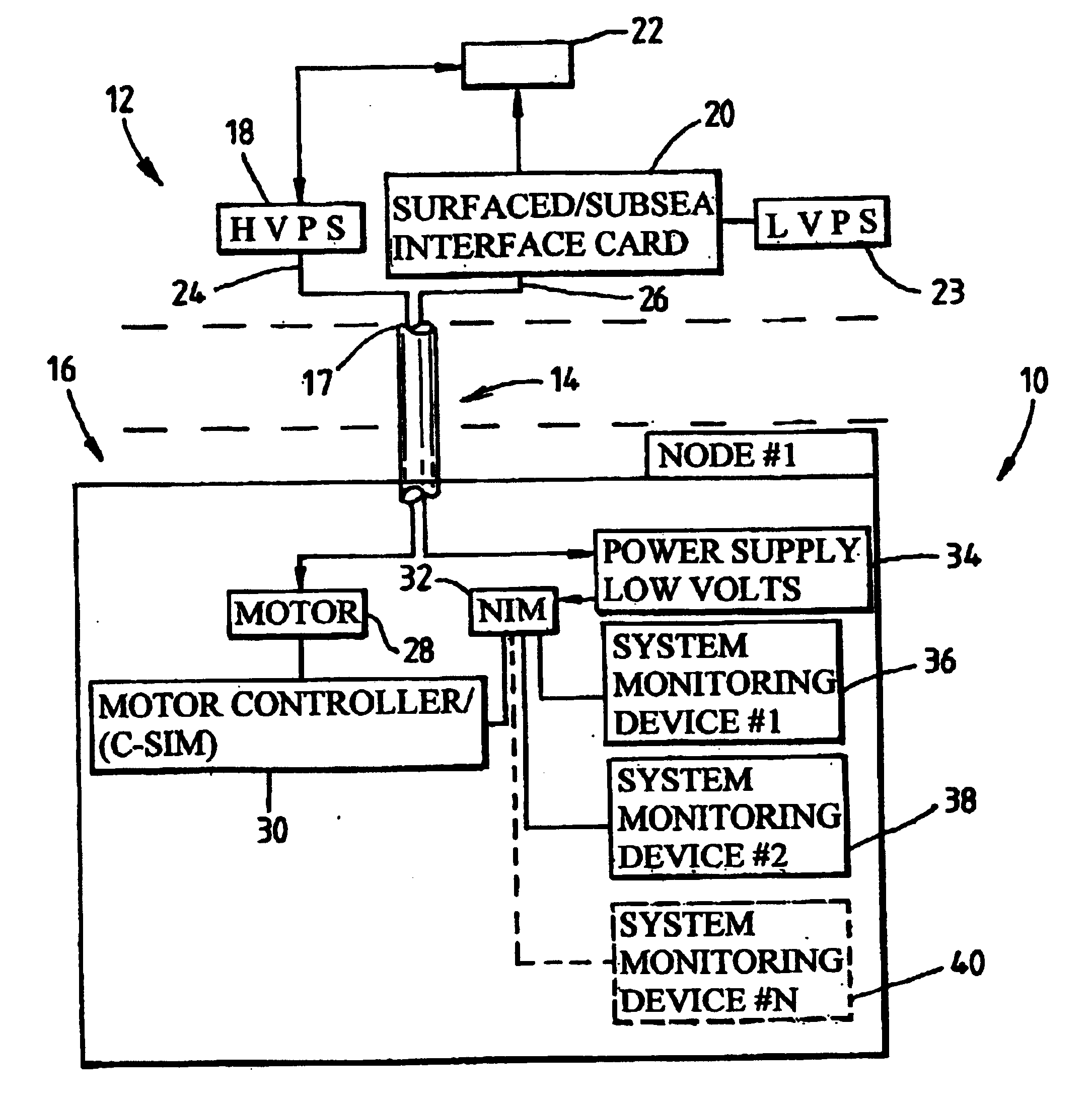
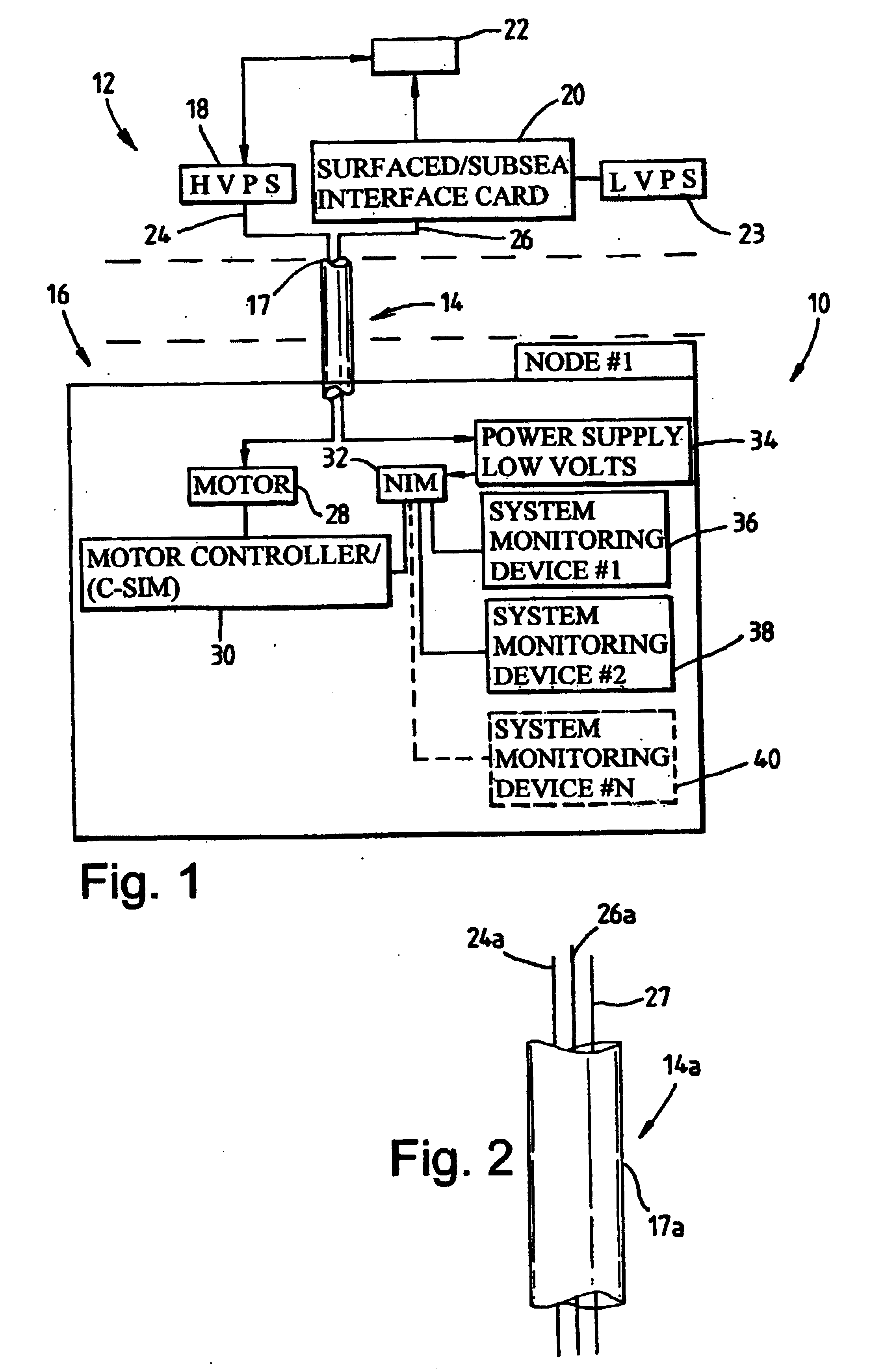
Reference is now made to FIG. 1 which depicts an in-well flow control system, generally indicated by reference numeral 10, which includes a surface portion 12 connected by a cable 14 to a downhole node #1, generally indicated by reference numeral 16. It will be understood that, in this embodiment, node 16 is only one node of 255 nodes which are connected to the surface portion 12.

The surface portion 12 has a 400 volt DC high voltage power supply (HVPS) 18 which is used to supply current up to 5 amps power downhole electronics in the nodes 16, on surface / subsea interface card 20 which are both coupled to a computer controlled data acquisition and command module (CCDACM) 22 which utilises Expro proprietary control and monitoring software (MZS) and a low voltage power supply (LVPS) 23 coupled to the interface card 20. The high voltage power supply 18 and subsea interface card 20 are coupled via cable 14 to the node 16. The surface / subsea interface card provides low voltage power, usual...


PUM


Abstract

An in-well monitoring and flow control system with an improved power supply. A separate high voltage (18) and low voltage power supply (23) is provided together with a cable (14) which has at least two separate cores; one core (24) for high voltage power and the other core (26) for low voltage power and control monitoring communications.

Description

FIELD OF THE INVENTIONThe present invention relates to control and monitoring systems for wells and particularly, but not exclusively, for hydraulic control of downhole flow control systems. The invention also relates to an in-well power supply for use with an in-well flow control and monitoring system.BACKGROUND OF THE INVENTIONControl systems for providing hydraulic control of valves from the surface are known. One example is the PES “SCRAMS” system which provides electro-hydraulic control of in-well valves from the surface. This system has solenoids which are supplied at a voltage of 120 volts for operating valves at 3,000 to 4,000 psi. Other systems are based on using electrical energy only to control valve operation and do not require hydraulic control. This means that a higher voltage, for example, 400 DC is needed to generate sufficient power to operate the valves. In practice, this is achieved by the use of a downhole power supply system incorporating high power electronic c...

Claims


Application Information

Patent Timeline
Patent Type & Authority Patents(United States)
IPC IPC(8): E21B17/00E21B17/20E21B34/00E21B34/16E21B47/12E21B47/00H04B3/02H04B3/44
CPCE21B17/206E21B34/16H04B3/44E21B47/12E21B47/0001E21B47/001
Inventor RICHARDS, ANDREWWEBSTER, WILLIAM GEORGE NIGEL PARKINSON
Owner EXPRO NORTH SEA
Learn More