Vehicle all-wheel drive system

a technology of all-wheel drive and vehicle, which is applied in the direction of propulsion parts, transportation and packaging, tractors, etc., can solve the problems of undermining the behavior of the associated vehicle, and achieve the effects of simple and effective, simple and effective, and simple and effectiv

Inactive Publication Date: 2005-04-12
SMITH ROGER
View PDF14 Cites 36 Cited by
  • Summary
  • Abstract
  • Description
  • Claims
  • Application Information

AI Technical Summary

Benefits of technology

According to a further feature of the hydraulic embodiment, the pump includes a piston engaging one end of the yoke and the piston is exposed to motor input pressure and operates to vary the pivotal aspect of the yoke in response to variations in motor input pressure. This specific arrangement provides an efficient means of matching the pump output pressure to the motor input pressure.
In an electrical embodiment of the invention, the motor comprises an electric motor; the device for generating energy comprises an electric generator; the energy storage device comprises a device capable of storing electrical energy such for example as a battery pack or a capacitor bank; the sensing means comprises a DC tachometer driven by the electric motor; and the directional device comprises a directional circuit switch assembly. This arrangement provides a simple electrical arrangement for sensing wheel load and routing electrical energy within the system.
According to a further feature of the electrical embodiment, the directional circuit assembly includes a control switch operative with the motor in a overrunning condition to direct the motor output to ...

Problems solved by technology

However, the efficient operation of an independent all wheel drive system is dependent on maintaining traction at each of the wheels at all ...

Method used


Image

  • Vehicle all-wheel drive system
  • Vehicle all-wheel drive system
  • Vehicle all-wheel drive system

Examples


Embodiment Construction

Three all wheel drive systems are disclosed. A hydraulic system is disclosed in FIGS. 1–15, a hydromechanical system is disclosed in FIG. 16, and an electrical system is disclosed in FIGS. 17–19.

Hydraulic all Wheel Drive System

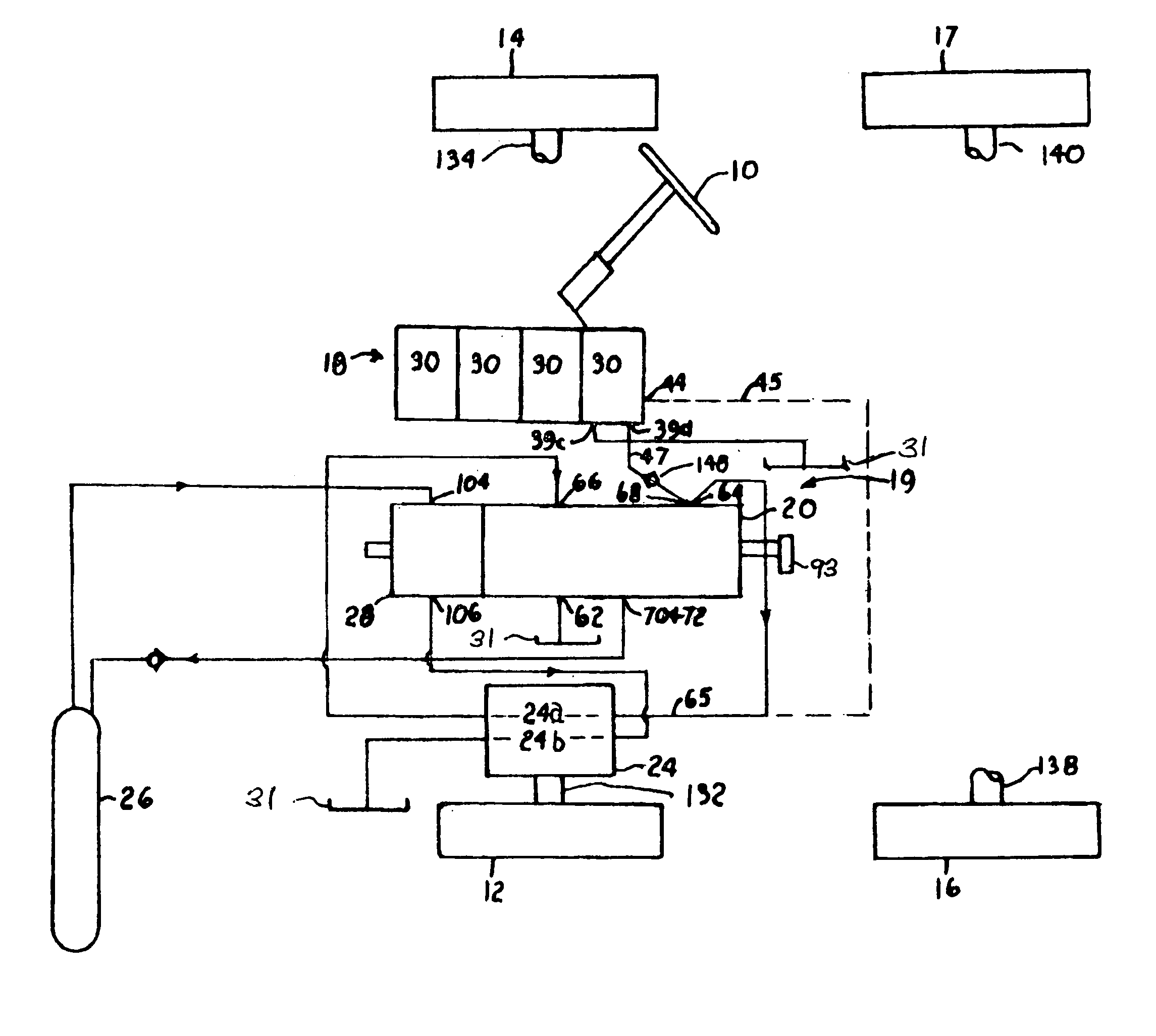
The motor vehicle shown schematically in the block diagram of FIG. 1 includes a steering wheel 10, a left front wheel 12, a right front wheel 14, a left rear wheel 16 and a right rear wheel 17.

The hydraulic drive system of the invention includes a central power unit 18 serving as the power unit for all four wheels 12, 14, 16, 17, and, for each wheel, a control unit 19 comprising a forward / reverse valve 20, a drive motor 24, an accumulator 26, and an accumulator output directional valve 28. Elements 20, 24, 26 and 28 are illustrated in FIG. 1 only with respect to the left front wheel 12, but it will be understood that a control unit 19, comprising a set of elements 20, 24, 26 and 28, is provided with respect to each wheel.

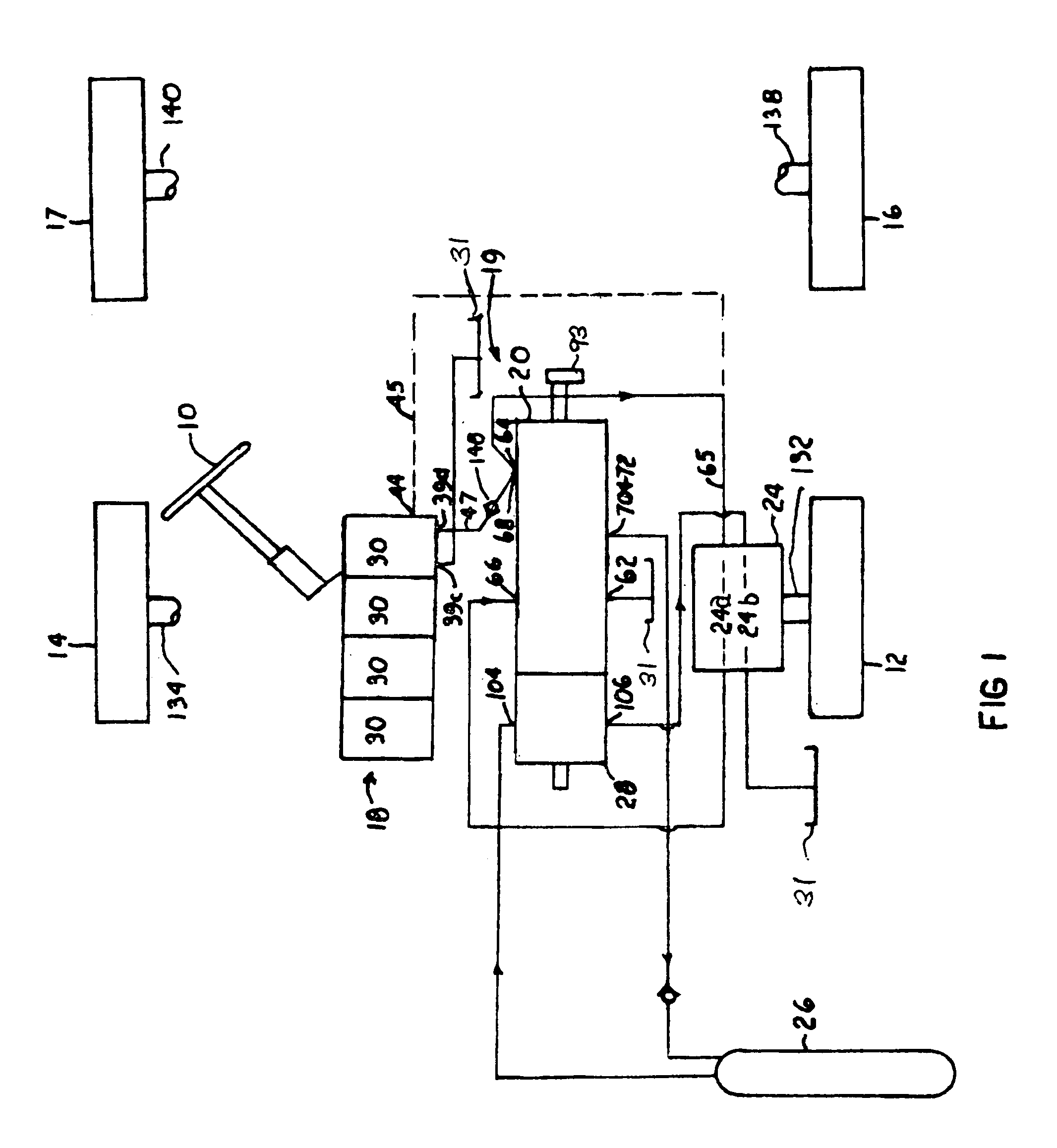
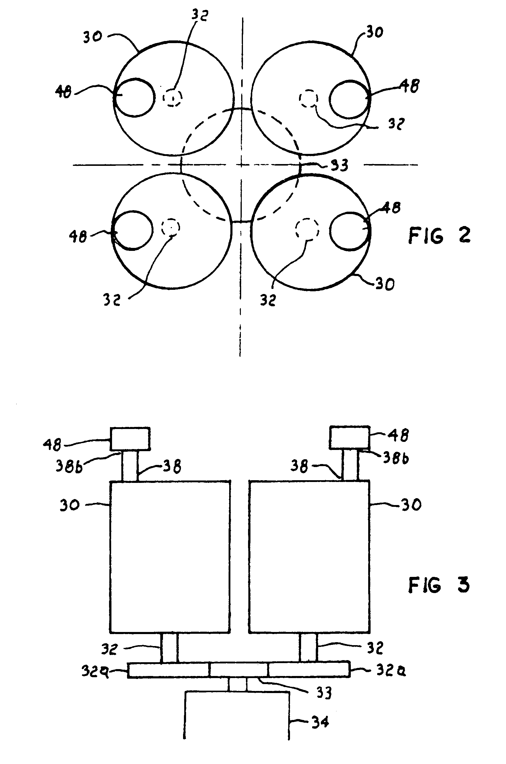
Central power unit 18 (FIGS. 2 and 3) ...


PUM


Abstract

An all wheel drive system for a motor vehicle in which wheel slippage is effectively controlled and regenerative energy is effectively stored for subsequent utilization in the system. A hydraulic embodiment of the invention includes a hydraulic motor, a pump, a tank, an accumulator for storing pressurized fluid, and a device for sensing system back pressure. In response to a loss of system back pressure the pressure of the fluid being supplied to the motor is reduced and the motor discharge is directed to the accumulator, and in response to a sensed resumption of system back pressure regenerative energy from the accumulator is directed to the motor to assist in powering the motor. An electric embodiment of the invention includes an electric motor, an electric generator, a device for storing electrical energy such as a battery pack or a capacitor bank, a DC tachometer driven by the motor and operative to sense the motor power requirements, and a directional circuit switch assembly. In response to a drop in the power requirements of the motor representing wheel slippage the energy supplied to the motor is reduced; in response to a sensed overrunning condition of the motor wherein the motor is functioning as a generator the output of the generator is routed to the energy storage device; and in response to a sensed resumption of motor power requirements regenerative energy is directed from the energy storage device to the motor to assist in powering of the motor.

Description

BACKGROUND OF THE INVENTIONThis invention relates to a vehicle drive system and, more particularly, to an all-wheel vehicle drive system in which each of the wheels is independently driven.All wheel motor vehicle drive systems are inherently superior to two wheel drive systems with respect to delivering vehicle power to the road surface. However, the efficient operation of an independent all wheel drive system is dependent on maintaining traction at each of the wheels at all times since wheel slippage adversely affects the efficiency of the drive system and significantly derogates the behavior of the associated vehicle.SUMMARY OF THE INVENTIONThis invention is directed to the provision of an improved all wheel drive system.More particularly, this invention is directed to the provision of an all wheel drive system in which wheel slippage is effectively controlled.The motor vehicle wheel drive system of the invention is of the type including a device for generating energy, a motor rec...

Claims


Application Information

Patent Timeline
IPC IPC(8): B60K6/12B60K6/04B60K6/00B60K17/356B60K17/34B60K28/16B60K6/46
CPCB60K6/12B60K6/46B60K17/356B60K28/165Y02T10/6265Y02T10/6208Y02T10/6217Y02T10/62
Inventor SMITH, ROGER
Owner SMITH ROGER
Why Eureka
Try Eureka