Microwave measurement of phase equilibria

a phase equilibria and microwave technology, applied in the direction of liquid/fluent solid measurement, fluid pressure measurement, instruments, etc., can solve the problems of difficult thermodynamic prediction of the phase behaviour of natural gas and gas condensate mixture, blockage may develop, and the thermodynamic prediction of the phase behaviour is difficult to achieve. , to achieve the effect of facilitating detection and measuremen

Inactive Publication Date: 2005-04-12
UNIV OF WESTERN AUSTRALIA
View PDF10 Cites 10 Cited by
  • Summary
  • Abstract
  • Description
  • Claims
  • Application Information

AI Technical Summary

Benefits of technology

Advantageously said electromagnetic resonant cavity comprises a reentrant geometry designed to facilitate detection and measurement of any liquid phase formed. Preferably the reentrant geometry causes two of the resonant modes of the cavity to depend sensitively on the electric fields in the region where liquid is most likely to form. Alternatively, rather than monitor two modes of the one cavity, the resonances of two distinct microwave cavities in fluid communication are monitored. However, the use of a single reentrant cavity with the particular geometry described below is thought to be most convenient.

Problems solved by technology

Natural gas and gas condensate mixtures are extremely complex as they contain a large number of unique hydrocarbon molecules.
The large number of different species in a naturally occurring hydrocarbon mixture makes thermodynamic prediction of its phase behaviour very difficult.
If this lower dew point is reached and sufficient liquid forms in the pipeline, a blockage may develop.
The pressure build-up on the up-stream side of the blockage will eventually cause the blockage to move, however this moving mass of liquid will have a momentum which could have potentially disastrous effects on the pipeline and / or the end consumer.
However, there are significant disadvantages with the conventional PVT cell when used for the measurement of phase equilibria of gas condensate fluids.
In particular, as well as being expensive, the equipment is massive, and the large samples required (typically 4000 cm3) take up to 24 hours to come to thermal and chemical equilibrium.
Consequently, the measurement of only one or two data points per day is possible, and it therefore takes a long time to collect sufficient data points to develop a phase envelope.
Despite their disadvantages, volumetric techniques are the only way currently available to actually measure the volume of liquid.
However, Moldover's resonator had a fixed volume, and therefore different sample densities could only be obtained by varying the amount of gas in the cavity.
Furthermore, Moldover's system was only tested on a synthetic binary mixture of composition such that the discontinuous change in the vapour phase was dramatic as the dew point curve was crossed.

Method used


Image

  • Microwave measurement of phase equilibria
  • Microwave measurement of phase equilibria
  • Microwave measurement of phase equilibria

Examples


second embodiment

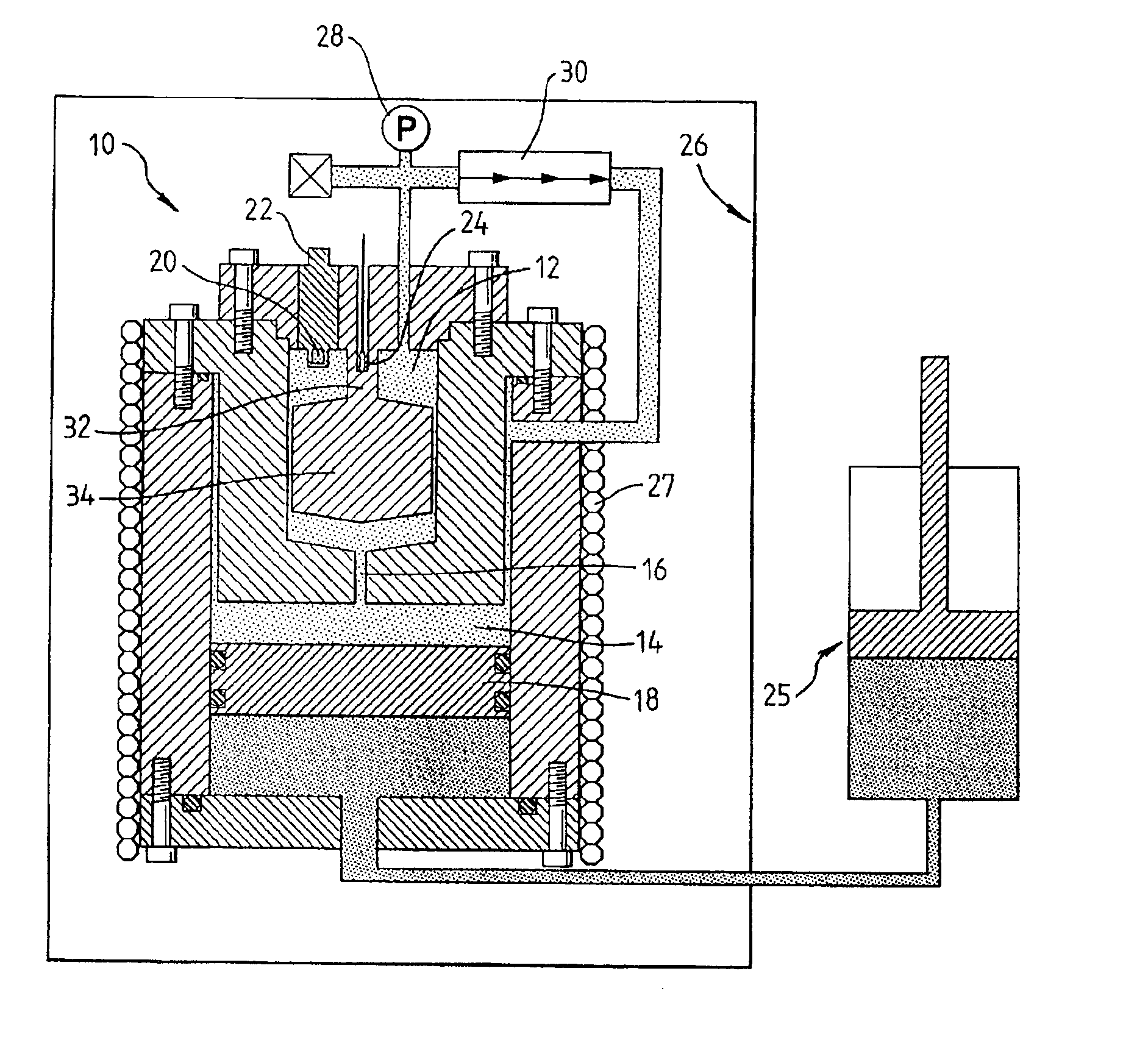
Two embodiments of the present invention are described in detail. The first, illustrated in FIG. 2, is an experimental apparatus 10 that demonstrates the successful combination of a variable volume pressure cylinder 14 in fluid communication with a microwave cavity 12. This embodiment generated most of the experimental data presented in the following section. The second embodiment, illustrated in FIGS. 3 and 4, is a more preferred embodiment. It is based on the first, but has been refined such that it has sufficient sensitivity to detect dew points in lean gas condensates and measure liquid volumes more accurately.

first embodiment

a variable volume microwave resonator apparatus 10 in accordance with the present invention is illustrated ed in FIG. 2. Tho apparatus consists of a stainless steel pressure cylinder 14 terminated at one end by a brass reentrant cavity 12 and at the other by a floating piston 18. The reentrant cavity 12 is similar to Moldover's, however, the hole 16 in the base of the cavity 12 is dimensioned to ensure high attenuation of radio frequency (rf) fields without impeding fluid flow to or from the pressure cylinder 14. The resonant frequency of the cavity 12 is therefore completely insensitive to variations in the position of the piston 18. The hydraulically driven piston 18 mounted within the pressure chamber 14 allows the total volume occupied by the fluid to be varied.

To determine and track the resonant frequency of the cavity 12, a frequency discriminator circuit is used (not shown). A simpler but more expensive method is to use a vector network analyser to determine the complex scatt...


PUM

PropertyMeasurementUnit
temperaturesaaaaaaaaaa
energy densityaaaaaaaaaa
pressuresaaaaaaaaaa

Abstract

A microwave resonator apparatus (35) includes a microwave resonant cavity (36) in fluid communication chamber (38) are dimensioned to ensure high attenuation of resonant electromagnetic fields without impeding fluid flow. The resonant properties of the cavity (36) are therefore completely insensitive to variations in the volume of the pressure chamber (38). The resonator has a specialised reentrant geometry. Consequently, two of the cavity's resonant modes depend sensitively upon the formation and volume of any liquid phase present in the cavity. The apparatus and the method are suitable for measuring dielectric properties and phase envelope of fluid mixtures (such as a gas condensate fluid). The apparatus can be used for making several phase envelope measurements without risk of contamination.

Description

FIELD OF THE INVENTIONThe present invention relates to a microwave technique for measuring the phase behaviour of fluids and relates particularly, though not exclusively, to a microwave apparatus and method for measuring the dielectric properties and phase envelope of natural gas and gas condensate fluids.BACKGROUND TO THE INVENTIONThe role of natural gas and gas condensate fluids in petroleum and hydrocarbon production is one of increasing importance. Natural gas and gas condensates are lean fluids, i.e. they consist predominantly of the low order alkanes—methane, ethane and propane, with decreasing amounts of the higher order alkanes (butane, pentane, hexane etc.). Within a typical reservoir, these lean fluid mixtures exist at high temperatures (˜120° C.) and pressures (˜350 atm). At these conditions, the fluid is in a single-phase, similar to a dense gas. However the exists a set of (lower) temperatures and pressures at which the fluid mixture exists in two phases at equilibrium....

Claims


Application Information

Patent Timeline
Patent Type & Authority Patents(United States)
IPC IPC(8): G01N22/00
CPCG01N22/00
Inventor MAY, ERIC F.EDWARDS, TERRY J.MANN, ANTHONY G.EDWARDS, CYRIL
Owner UNIV OF WESTERN AUSTRALIA
Why Eureka
Try Eureka