Offsetting patch antennas on an ominidirectional multi-facetted array to allow space for an interconnection board

a patch antenna and interconnection board technology, applied in the field of patch antenna arrays, can solve the problems of imposing mounting stresses on the antenna array and tower, reducing the width requirements of the facet, and avoiding any discontinuity in rf propagation

Active Publication Date: 2005-04-12
APPLE INC
View PDF7 Cites 15 Cited by
  • Summary
  • Abstract
  • Description
  • Claims
  • Application Information

AI Technical Summary

Benefits of technology

Advantageously, the at least one radio frequency interface module is disposed across an inside corner formed at the connectively abutting sides of two adjacent facets of the plurality of facets. This placement of the radio frequency interface module has the advantage of further reducing the width requirements for the facet upon which the radio frequency module is at least partially sited.
In accordance with another aspect of the present invention there is provided a method for forming an antenna array including the steps of disposing a plurality of facets around an axis, each of the plurality of facets having sides connectively abutting the sides of an adjacent facet, the plurality of facets forming a faceted tube, and disposing at least one patch antenna on each of the plurality of facets. Further, th

Problems solved by technology

Existing patch antenna designs have a lower bound on facet sizes because of engineering limitations.
These limitations are imposed due to space requirements for: patch antenna width for efficient operation at the required Gigahertz frequencies used in today's cellular systems; the patch antenna ground plane; the interconnection tracking; the printed circu

Method used


Image

  • Offsetting patch antennas on an ominidirectional multi-facetted array to allow space for an interconnection board
  • Offsetting patch antennas on an ominidirectional multi-facetted array to allow space for an interconnection board
  • Offsetting patch antennas on an ominidirectional multi-facetted array to allow space for an interconnection board

Examples


Embodiment Construction

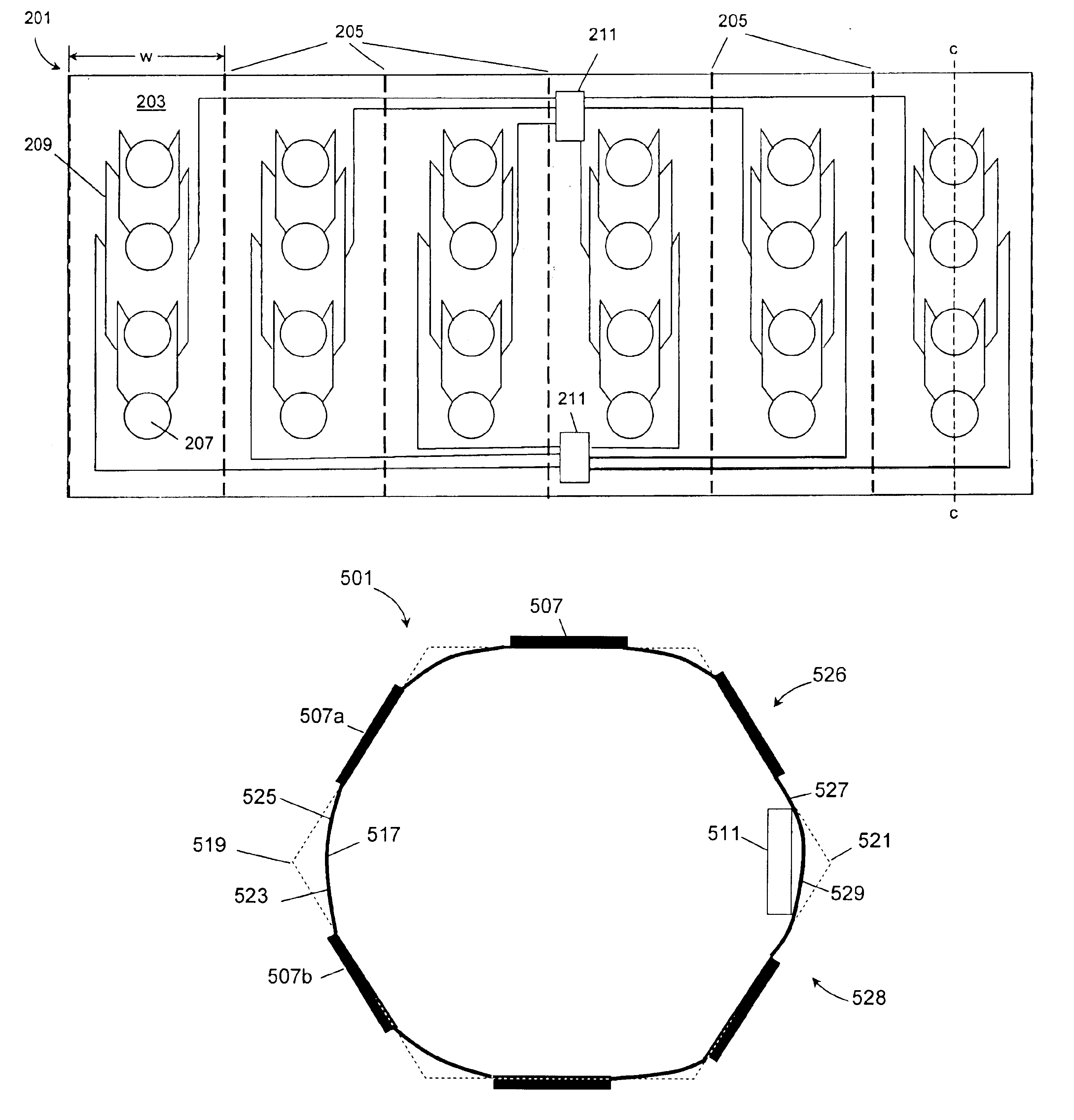
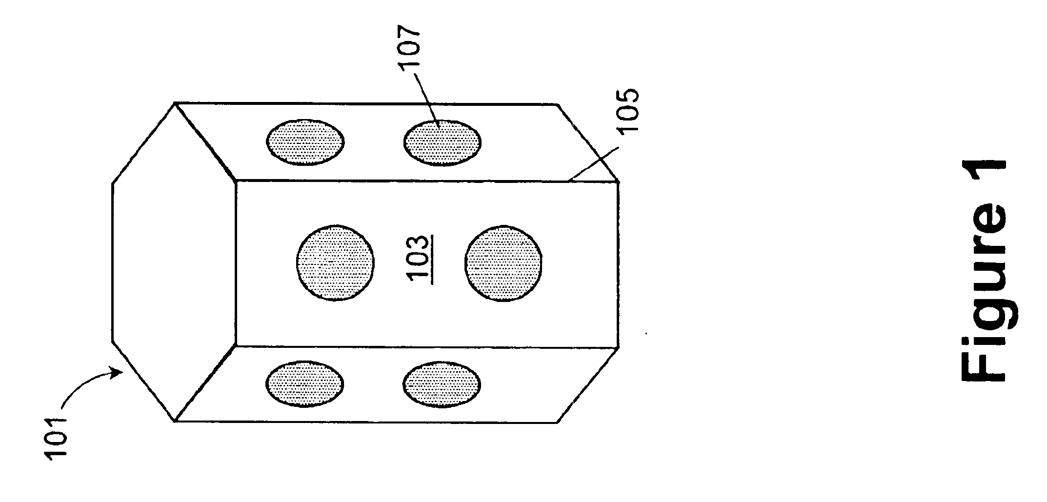
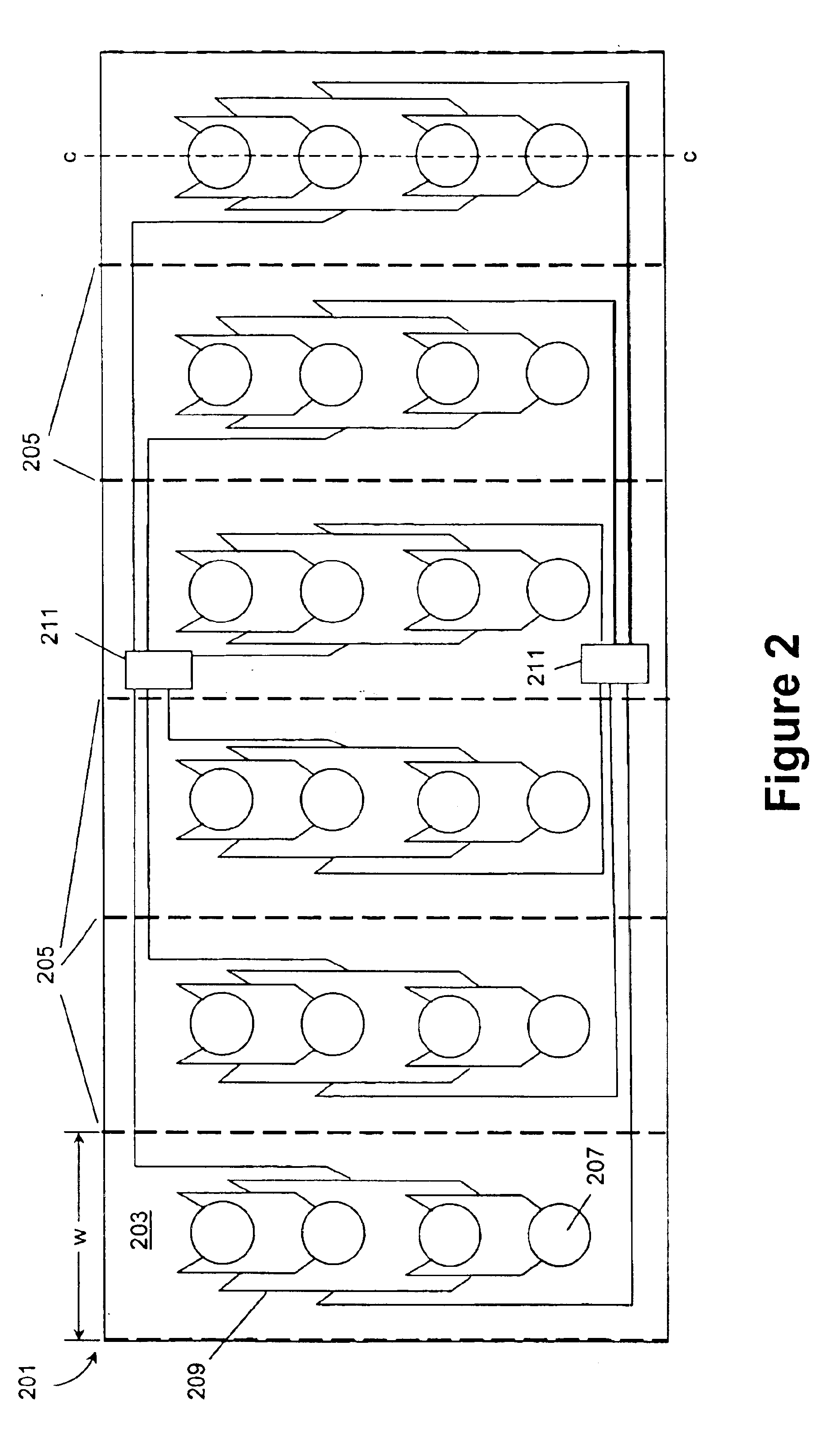
In the discussion that follows, like reference numbers refer to like elements in similar figures. Referring to FIG. 1 there may be seen an example multi-section antenna array 101 in perspective view. The array is formed by a number of facets 103, the total quantity being a function of the particular application but typically comprising six or eight in total. The facets are arranged with abutting sides 105 which form edges or corners of the resultant polygonal tube. The facets need not be separate units, but instead may be formed on a single or convenient number of sheets which are effectively creased or folded at the edges of the facets. Located upon the facets are the patch antenna elements 107 which radiate or receive the requisite radio frequency (RF) signal. As is generally known, the patch antenna elements 107 have an associated ground plane (not shown) located beneath the patch antenna element, and separated from the conductive surface of the patch antenna element by a dielect...


PUM


Abstract

A multi-facetted antenna array is disclosed for omnidirectional signalling. The multi-facetted antenna array includes a plurality of abutting facets having a planar region under the patch antenna structures, and curving regions between the planar regions and across the abutting edges of the facets. The planar regions under the patch antenna provide proper RF antenna performance, while the curved regions minimize the size of the assembled array. Further disclosed is a method of mounting the associated RF interface module across an inside corner formed by abutting facets. The disclosed multi-facetted antenna array is particularly useful for overcoming the unsightly size and wind loading problems of multi-facetted antenna arrays known in the art.

Description

FIELD OF THE INVENTIONThe present invention relates to patch antenna arrays and is particularly concerned with minimizing the overall array dimensions of an omnidirectional multi-facetted array.BACKGROUND OF THE INVENTIONWithin a wireless communication system, it is strongly desirable for cellular antenna arrays to have minimal size for reasons of ease of installation, greater stability under wind loading conditions, and minimal visual obtrusiveness.One variety of omnidirectional antenna used in cellular installations is a multi-facetted patch array. This type of antenna has a series of patch antenna on facets, and the facets are circumferentially disposed around an axis with each antenna facing outward. A minimum overall array size may be obtained when the facets abut one another, forming a faceted tube.Existing patch antenna designs have a lower bound on facet sizes because of engineering limitations. These limitations are imposed due to space requirements for: patch antenna width...

Claims


Application Information

Patent Timeline
IPC IPC(8): H01Q1/38H01Q1/24H01Q21/06H01Q21/20H01Q21/00
CPCH01Q1/246H01Q21/205H01Q9/0407
Inventor DUXBURY, GUYSHEFFIELD, ROBERTBOLZON, DAVIDABRAHAM, IANURQUHART, ANDREW
Owner APPLE INC
Why Eureka
Try Eureka