Active seat suspension for watercraft

a technology for active seat suspension and watercraft, which is applied in the direction of shock absorbers, special purpose vessels, vessel construction, etc., can solve the problems of increasing the fatigue of riders, affecting the stability of watercraft, and affecting the rider's comfor

Inactive Publication Date: 2005-04-19
BWI CO LTD SA
View PDF28 Cites 44 Cited by
  • Summary
  • Abstract
  • Description
  • Claims
  • Application Information

AI Technical Summary

Benefits of technology

[0015]Accordingly, it is a general aspect of the invention to provide a seat suspension damper for watercraft which is active so as to provide a variable cushioned or damping force which counteracts the many varied forces otherwise experienced by the occupant of a seat in a watercraft.
[0019]In accordance with another general aspect of the invention, the sensor can be any type of sensor measuring one or more of the following physical characteristics to determine the damper resistance to be applied to movement of the seat: a) position (at any clocked time), b) velocity, c) acceleration, d) pressure and e) the sprung mass or weight of an occupied seat. In accordance with a preferred embodiment of the invention, a single sensor indicative of the vertical motion of the seat imparted by the sprung weight of an occupied seat is sufficient to account for forces attributed to roll, pitch and yaw on the seat, especially when the damper is a single, uni-directional damper oriented in a vertical direction whereby the cost of the suspension is minimized. In more sophisticated applications where several active seat dampers may be employed, several sensors may be optionally employed and / or lateral force sensors additionally employed to provide a more sensitive system that can better maintain the position of the seat occupant's center of gravity.
[0023]It is thus a general object of the invention to provide a watercraft seat suspension which gives improved stability, comfort and / or safety to the seat occupant.
[0024]It is another objective of the invention to provide a watercraft suspension system which provide a smooth ride to the boat occupants substantially free from jarring blows to the watercraft's hull caused by wakes and rough water. Importantly, the system can also control the heave of the riders and help prevent personal injury from being thrown off the seat.
[0026]Additional advantages and features of the invention include the fact that the damper can be readily fitted into existing suspension systems and / or can be instrumented to provide inputs indicative of the force conditions affecting watercraft with fractional micro second damper adjustments for such forces, all in a closed but active environment; and / or adjustable, in the active sense, by the user simply toggling a switch or dial and / or utilized in confined installation spaces where the stroke of the damper is limited.

Problems solved by technology

Standing while operating the vessel in such situations is practically impossible and the operator must be seated to avoid being thrown around uncontrollably.
Riders often experience noticeable vibrations, shocks and bumps as the relatively light-weight, small hull travels quickly across a body of water.
The resultant rough ride contributes to rider fatigue.
The landing, however, severely jars the rider, especially if the watercraft lands bow first.
In summary, the seats and / or seat suspensions employed in watercraft do use dampers, but the dampers are passive and do not have the ability to automatically adjust to the widely variant loads imposed on the seat in watercraft applications.
Additionally, there are space limitations present in many watercraft installations which, in turn, affect the ability of conventional shock absorbers to provide an effective damper over the travel range of the dampers.
Further, while air suspensions have been suggested to account for the different sprung masses to which the PWC seat may be exposed, an external source of fluid, i.e., air pump, has to be provided and the damper curve for air shocks is limited.

Method used


Image

  • Active seat suspension for watercraft
  • Active seat suspension for watercraft
  • Active seat suspension for watercraft

Examples


Embodiment Construction

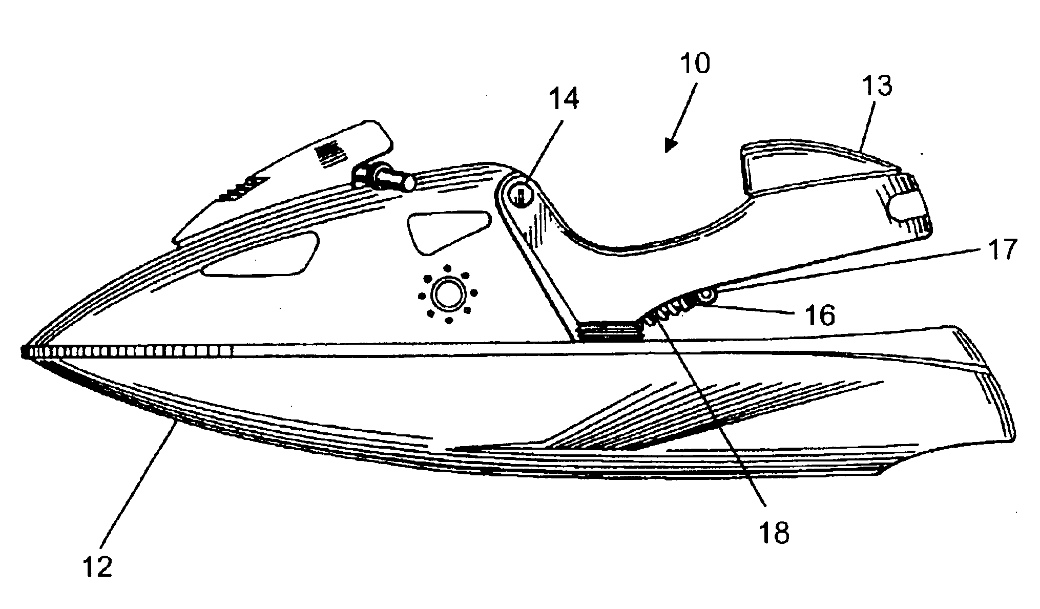
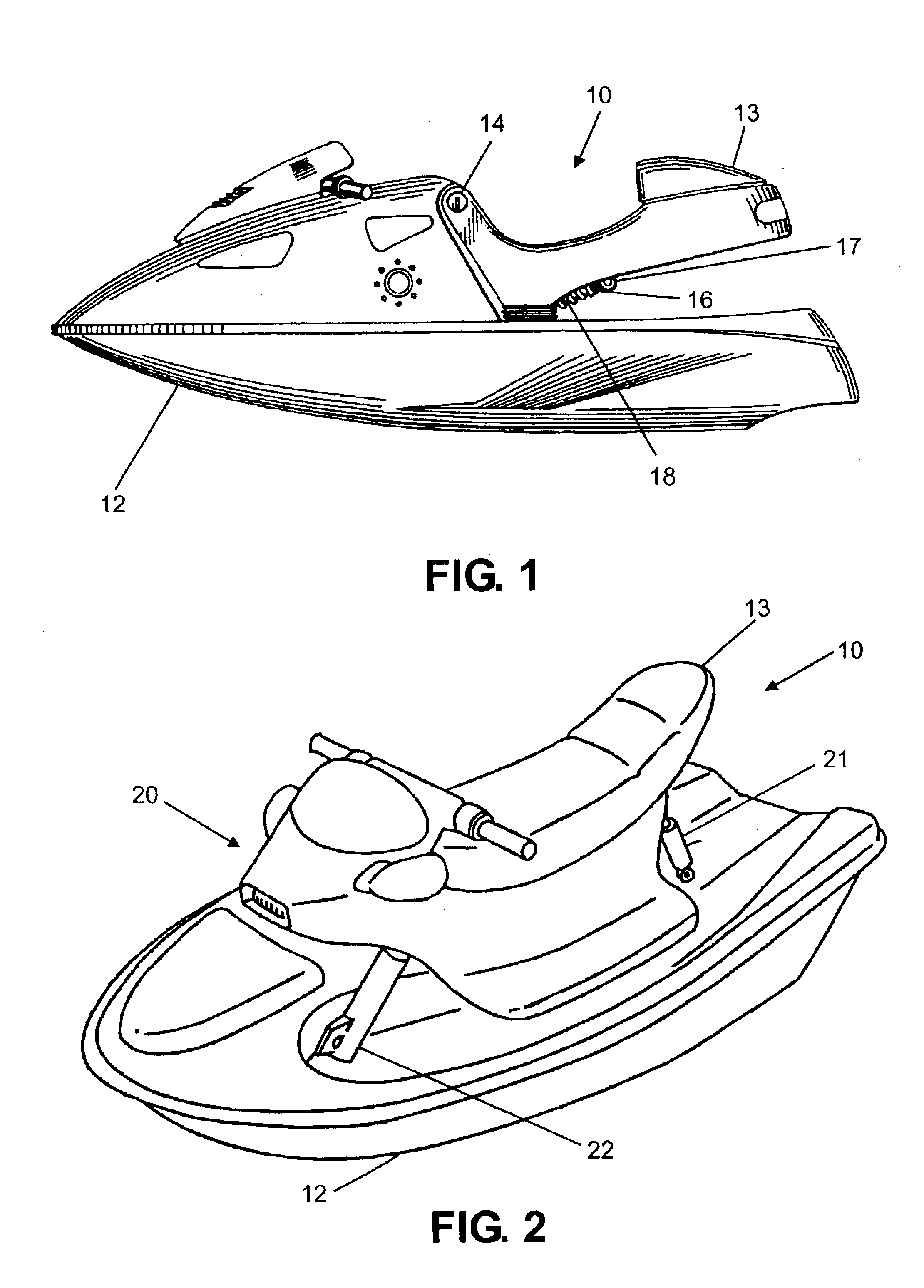
[0041]Referring now to the drawings wherein the showings are for the purpose of illustrating preferred and alternative embodiments of the invention only and not for the purpose of limiting the same, there is shown in FIG. 1 a depiction of a personal watercraft 10. Personal watercraft is used herein in accordance with its customary meaning, namely, a vessel using an inboard motor powering a jet pump as its primary source of motor power and which is designed to be operated by a person sitting or kneeling on the vessel rather than the conventional manner of sitting or standing inside the vessel.

[0042]In the embodiment of the invention disclosed in FIG. 1, personal watercraft 10 has a hull 12 usually made of fibreglass and a seat 13 shown as an elongated streamlined body. In this embodiment, seat 13 is pivotally mounted to hull 12 substantially at the front end of seat 13 by means of a pivot pin 14. This pivot arrangement mounts seat 13 to hull 12 in a cantilever fashion to permit up an...


PUM


Abstract

A watercraft seat suspension includes a damper mounted between a watercraft seat and the watercraft hull. The damper includes an electrically actuated mechanism controlling fluid flow from a first chamber to a second chamber within the damper. A sensor senses motion of the seat relative to the hull. A control unit interpolates the sensor signal and develops an actuating signal controlling the electrically actuated mechanism. In one arrangement, the electrically actuated mechanism is a solenoid actuated by the actuating signal to effect one of two different damping modes. In another arrangement, the electrically actuated mechanism includes a conductor coil and flux ring generating a magnetic field proportional to the actuating signal to vary the viscosity of magneto-rheological fluid in the damper.

Description

[0001]This invention relates generally to watercraft and, more particularly, to a shock absorbing or shock attenuating suspension system for a watercraft seat.BACKGROUND[0002]Power watercraft (boats) moving at speeds when impacting a wave, either natural or caused by another's boat wake, technically experience three forces about mutually octagonal axis. These forces are commonly referred to as “roll” which is a force about an axis which is in line with the direction that the boat is headed, “pitch” which is about an axis which is a line in the same plane as the roll axis but ninety degrees orthogonal to the roll axis, and “yaw” which is an axis along a line which is vertical to, or ninety degrees from, both the pitch and roll axis.[0003]In a traditional vessel, boat, cabin cruiser, etc., application, the operator of the watercraft is jarred substantially, even during mild seas. Standing while operating the vessel in such situations is practically impossible and the operator must be ...

Claims


Application Information

Patent Timeline
Patent Type & Authority Patents(United States)
IPC IPC(8): B63B29/06F16F9/53
CPCB63B29/06F16F9/535
Inventor FEDDERS, BRANDON J.
Owner BWI CO LTD SA
Why Eureka
Try Eureka