Intake system

a technology of intake system and filter case, which is applied in the direction of liquid degasification, auxillary pretreatment, separation process, etc., can solve the problems of difficult matching of such intake system to the operating range in question, negative effect of filter case volume or the like, and difficulty in forming uniform mixture, etc., to eliminate the influence of air filter contamination, easy assembly, and improved engine running performan

Active Publication Date: 2005-04-19
ANDREAS STIHL AG & CO KG
View PDF2 Cites 10 Cited by
  • Summary
  • Abstract
  • Description
  • Claims
  • Application Information

AI Technical Summary

Benefits of technology

[0006]For avoiding such problems, U.S. Pat. No. 5,485,817 discloses an arrangement wherein a filter case has a ventilation opening which is either connected to the atmosphere or to a low pressure zone of the cooling fan. The ventilation opening is intended to avoid an excitation vibration of the air column in the combustion air channel. Here, the air channel should be so dimensioned that an underpressure or an overpressure arises in the air filter case. In order to substantially eliminate the influence of the air filter contamination on the mixture formation, it is conventional to provide a compensation connection which connects a compensation chamber of the carburetor to the clean space of the air filter. For fluctuating pressures in the air filter chamber, a compensation is, however, not possible so that the air / fuel mixture cannot be optimally adjusted.
[0007]It is an object of the invention to provide such an intake system which is improved so that it is easy to assemble and leads to an improved running performance of the engine.
[0008]The intake system of the invention is for preparing combustion air for an internal combustion engine of a portable handheld work apparatus and includes: a carburetor having an intake channel defining an intake opening; an air filter mounted upstream of the carburetor; a filter case surrounding the air filter and having an inlet opening; a cooling air fan unit of the engine for generating a flow of cooling air; a combustion air channel having a take-up inlet in the cooling air fan unit; the combustion air channel extending to the inlet opening of the filter case; the filter case having an inner space and having ventilation opening means for connecting the inner space to the ambient air; and, the ventilation opening means having a flow cross section so dimensioned that the air flows through the inlet opening, the intake opening of the carburetor and the ventilation opening are balanced at rated rpm of the engine and that a uniform pressure level adjusts in the inner space of the filter case.
[0009]The compensated pressure level permits the connection of a compensation connection to the clean space of the air filter. The compensated pressure level adjusts at least at rated rpm and especially in a wide rpm range. In these regions, the ratio of the fuel and air can thereby be optimally adjusted.
[0010]In an advantageous further embodiment, the area of the ventilation opening is matched to the volume of the interior space of the filter case and especially to the piston displacement of the engine. For usual structural sizes of internal combustion engines for handheld portable work apparatus and a corresponding design of the air filters, it has been shown that an area of the ventilation opening in the range between 100 mm2 and 800 mm2 is well matched. There also results especially a good matching with an area of the ventilation opening which corresponds approximately to the cross-sectional area of the intake opening of the carburetor. It has been shown that, within the matching limits set forth above, a targeted direct matching of the engine adjustment is given for a quiet and powerful engine running over the entire range of the operating parameters.
[0011]In the known arrangements, the ventilation opening to the atmosphere is arranged close to the inlet opening of the combustion air channel in the filter case. Dirt particles or the like, which enter into the filter case from the inlet opening at high velocity, are guided to a considerable extent past the ventilation opening and are drawn by suction by the carburetor to the air filter. As a consequence, an unwanted early dirtying of the air filter occurs. In order to avoid this, it is suggested to arrange the inlet opening above a ventilation opening referred to the gravity direction for a usual operating position of the work apparatus. Dust or dirt particles or the like, which are conducted with the airflow in the combustion air channel, slow their path velocity in the comparatively large volume of the filter case. Under the action of gravity, the particles can drop and (without being drawn by suction to the air filter) can reach the ambient via the ventilation opening.

Problems solved by technology

Matching such an intake system to the operating range in question has been shown to be difficult.
This, in turn, can have considerable disadvantageous effects on the intake performance in the region of the carburetor and therefore have associated negative effects on the desired uniform mixture formation.
The matching of the engine and carburetor to each other as well as their matching to the design of the combustion air channel, the filter case volume or the like can be difficult.
The arrangement of a compensator is complex and does not always lead to the wanted success.
Especially, it can happen that a found matching functions only in a narrow operating parameter range outside of which no effective matching is given.
For fluctuating pressures in the air filter chamber, a compensation is, however, not possible so that the air / fuel mixture cannot be optimally adjusted.

Method used


Image

  • Intake system
  • Intake system
  • Intake system

Examples


Embodiment Construction

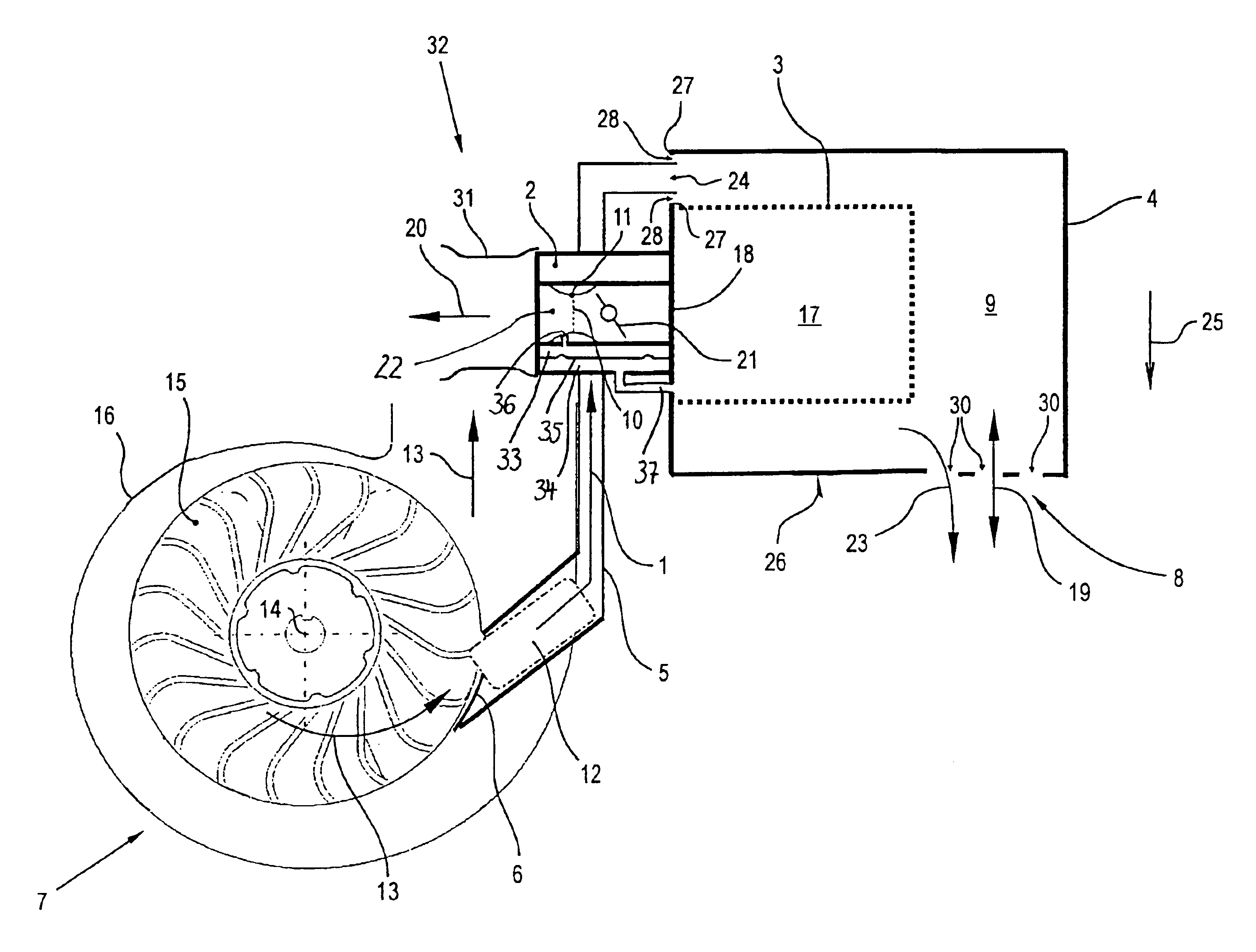
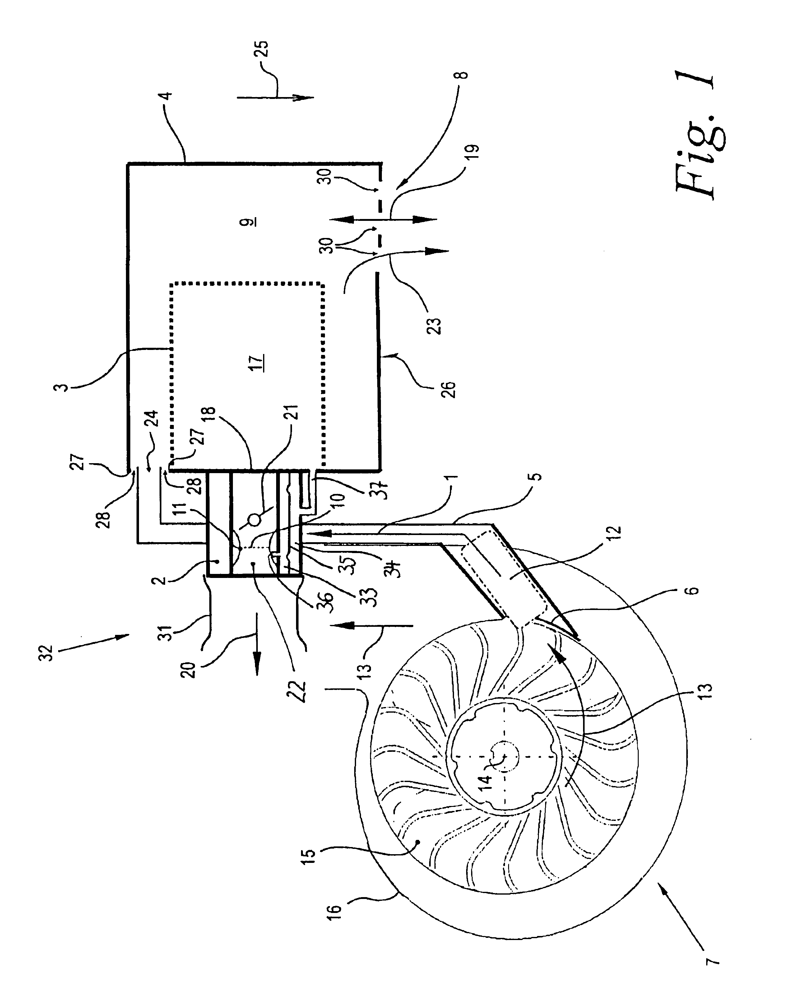
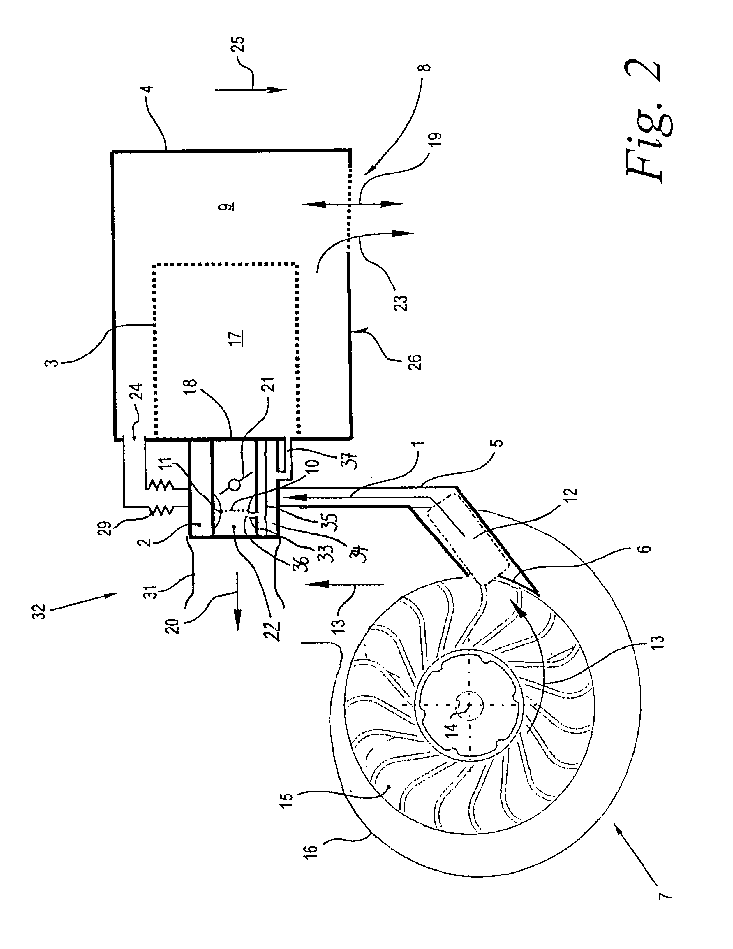
[0024]FIG. 1 shows an intake system of a portable handheld work apparatus (not shown) such as a chain saw, brushcutter, suction / blower apparatus or the like. The intake system shown is for preparing combustion air for an internal combustion engine (not shown) for driving a portable handheld work apparatus. The combustion air is shown by arrow 1. The intake system includes a carburetor 2, an air filter 3 connected upstream of the carburetor 2 and a filter case 4 surrounding the air filter 3 from the outside. A swing gap 32 is formed between the carburetor 2, which is rigidly mounted on the work apparatus, and the elastically mounted engine. An elastic sleeve 31 is provided to bridge the swing gap 32 and connect the carburetor 2 to the engine.

[0025]A cooling air fan 7 is provided as part of the intake system shown and is for cooling the internal combustion engine. A combustion air channel 5 leads from a take-up opening 6 in the cooling air fan 7 to the filter case 4. In the embodiment...


PUM

PropertyMeasurementUnit
areaaaaaaaaaaa
areaaaaaaaaaaa
pressureaaaaaaaaaa

Abstract

An intake system for preparing combustion air (1) is for an internal combustion engine of a portable handheld work apparatus. The intake system includes: a carburetor (2); an air filter (3) which is connected upstream of the carburetor (2); and, a filter case (4) which closes the air filter (3) from the outside. A combustion air channel (5) leads from a take-up opening (6) in a cooling air fan (7) of the engine to an inlet opening (24) in the filter case (4). The filter case (4) includes at least one defined ventilation opening (8) for connecting an inner space (9) of the filter case (4) to the ambient air. The flow cross section of the ventilation opening (8) is so designed that the airflows through the inlet opening (24), the intake opening (18) of the carburetor (2) and the ventilation opening (8) are compensated at the rated rpm of the engine and that a uniform pressure level adjusts in the inner space (9) of the filter case (4).

Description

CROSS REFERENCE TO RELATED APPLICATION[0001]This application claims priority of German patent application no. 103 01 731.3, filed Jan. 18, 2003, the entire content of which is incorporated herein by reference.FIELD OF THE INVENTION[0002]The invention relates to an intake system for preparing combustion air for an internal combustion engine of a portable handheld work apparatus.BACKGROUND OF THE INVENTION[0003]In work apparatus such as chain saws, brushcutters, suction / blower apparatus or the like, which are driven by internal combustion engines, intake systems are provided for preparing combustion air for the engine. In the intake systems, a carburetor having a forwardly connected air filter and a filter case is mounted surrounding the air filter on the outside. The combustion airflow is drawn by the engine through the carburetor and the air filter out of the interior space of the filter case. In known arrangements, a combustion air channel is provided leading to the filter case fro...

Claims


Application Information

Patent Timeline
Patent Type & Authority Patents(United States)
IPC IPC(8): F02M35/02F02M35/06F02B63/02F02B63/00
CPCF02M35/06F02B63/02Y10S55/28
Inventor MAIER, GEORGKIESEWETTER, FRITZBAHNER, ANDREASTUCKERMANN, RALFKLIMMEK, AXEL
Owner ANDREAS STIHL AG & CO KG
Why Eureka
Try Eureka