Transfer case for hybrid vehicle

Inactive Publication Date: 2005-04-19
MAGNA DRIVETRAIN OF AMERICA
View PDF14 Cites 29 Cited by
  • Summary
  • Abstract
  • Description
  • Claims
  • Application Information

AI Technical Summary

Benefits of technology

[0010]As a further object, the hybrid drive system of the present invention utilizes a transfer case having a two-speed planetary gearset which can provide a direct high-range drive ratio and a reduction low-range drive ratio in any of the available (i.e., electric only, internal combustion engine only and hybrid) drive modes.
[0011]These and other objects are provided by a hybrid two-speed transfer case having a mainshaft, a rear output shaft, a front output shaft, an electric motor/generator connected to the mainshaft, and an input clutch assembly operable for selectively coupling the transmission output shaft to the mainshaft. The transfer case further includes a planetary gearset having a sun gear driven by the mainshaft, a ring gear, and planet gears supported from a carrier that are meshed with the sun gear and the ring gear. The carrier is arranged to drive a rear output shaft and a drive sprocket of a transfer assembly which also includes a driven sprocket and a power chain connecting the sprockets. A direct clutch assembly is operable in an applied state to couple the carrier for rotation with the mainshaft and is further operable in a released state to permit relative

Problems solved by technology

Unfortunately, these alternative powertrain systems suffer from several disadvantages and, for all practical purposes, are still under development.
Regardless of the type of hybrid drive system used, hybrid vehicles are highly modified versions of conventional vehicles that are expensive du

Method used


Image

  • Transfer case for hybrid vehicle
  • Transfer case for hybrid vehicle
  • Transfer case for hybrid vehicle

Examples


Embodiment Construction

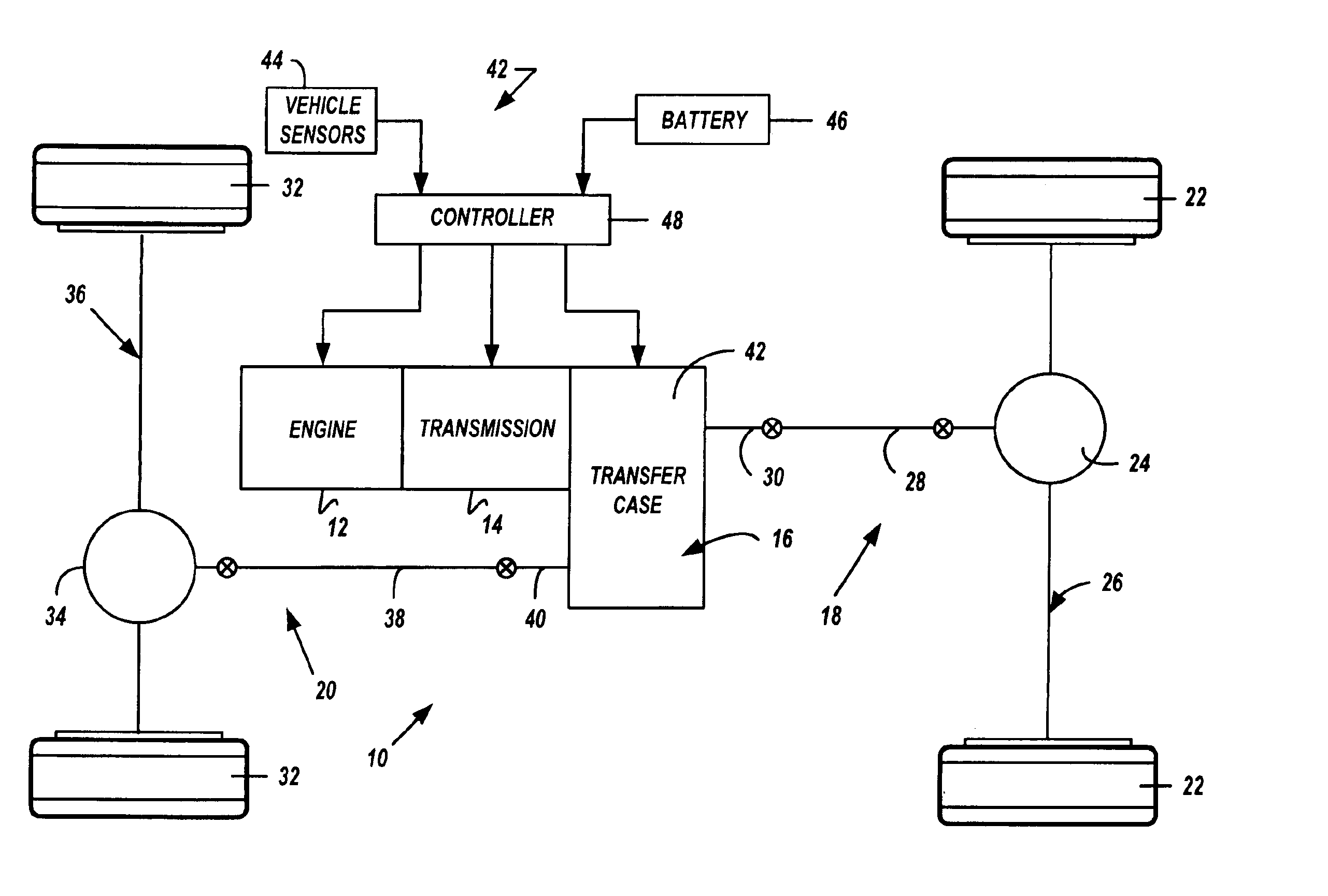
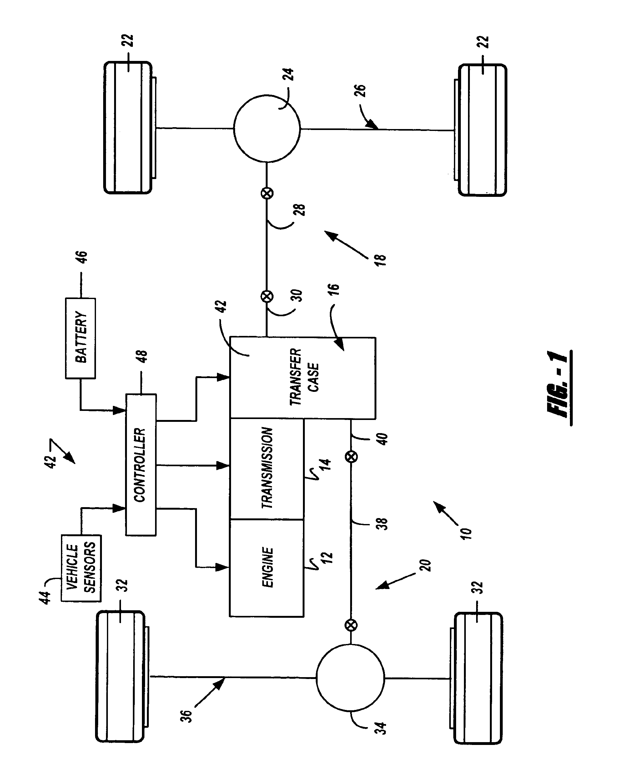
[0024]Referring to FIG. 1 of the drawings, a four-wheel drive powertrain 10 for a hybrid motor vehicle is shown to include an internal combustion engine 12, a transmission 14 and a transfer case 16 arranged to transferred motive power (i.e., drive torque) from engine 12 and transmission 14 to a primary driveline 18 and a secondary driveline 20. In the particular arrangement shown, primary driveline 18 is the rear driveline and includes a pair of rear wheels 22 connected to a rear differential unit 24 associated with a rear axle assembly 26. A rear prop shaft 28 interconnects rear differential unit 24 to a rear output shaft 30 of transfer case 16. Secondary driveline 20 is the front driveline and includes a pair of front wheels 32 connected to a front differential unit 34 associated with a front axle assembly 36. A front prop shaft 38 interconnects differential unit 34 to a front output shaft 40 of transfer case 16. Powertrain 10 is also shown to be associated with a powertrain contr...


PUM


Abstract

A hybrid transfer case includes a mainshaft, front and rear output shafts, an electric motor/generator connected to the mainshaft, and an input clutch for selectively coupling the transmission to the mainshaft. The transfer case further includes a planetary gearset having a sun gear driven by the mainshaft, a ring gear, and planet gears supported from a carrier. A direct clutch is operable to selectively couple the rear output shaft for rotation with the input shaft. A low brake is operable to selectively brake rotation of the ring gear. A transfer clutch controls the amount of drive torque delivered through a transfer assembly to the front output shaft. A hybrid control system is provided for controlling actuation of the various clutch and brake assemblies and the electric motor/generator to establish various drive modes.

Description

CROSS-REFERENCE TO RELATED APPLICATIONS[0001]This application is a continuation of U.S. patent application Ser. No. 10 / 429,395 filed on May 5, 2003, now U.S. Pat. No. 6,679,799 which is a continuation of U.S. patent application Ser. No. 10 / 000,196 filed Nov. 2, 2001, now U.S. Pat. No. 6,589,128.FIELD OF THE INVENTION[0002]The present invention relates generally to hybrid drive systems for motor vehicles, and, more specifically, to a hybrid transfer case for use in four-wheel drive vehicles.BACKGROUND OF THE INVENTION[0003]Automobile manufacturers are actively working to develop alternative powertrain systems in an effort to reduce the level of pollutants exhausted into the air by conventional powertrains equipped with internal combustion engines. Significant development has been directed to electric vehicles and fuel cell vehicles. Unfortunately, these alternative powertrain systems suffer from several disadvantages and, for all practical purposes, are still under development. Howev...

Claims


Application Information

Patent Timeline
IPC IPC(8): B60K6/04B60K6/00B60K17/344B60K23/08B60K6/365B60K6/40B60K6/48B60K6/52B60K6/54B60W10/02B60W10/10
CPCB60K6/365B60K6/48B60K6/52B60K6/54B60K17/344B60K23/0808B60W10/02B60W10/10B60K6/40Y10S903/916B60W20/00Y02T10/6221Y02T10/6265Y10S903/951Y10S903/945Y10S903/946Y10S903/91Y10S903/917Y02T10/62B60W20/40
Inventor BOWEN, THOMAS C.
Owner MAGNA DRIVETRAIN OF AMERICA
Why Eureka
Try Eureka