Method of recapturing a stent

a stent and recapturing technology, applied in the field of stents, can solve the problems of catastrophic failure of a balloon containing radioactive or cryogenic fluid, balloon to fail, etc., and achieve the effect of being ready to withdraw

Inactive Publication Date: 2005-04-19
BARD PERIPHERAL VASCULAR
View PDF42 Cites 293 Cited by
  • Summary
  • Abstract
  • Description
  • Claims
  • Application Information

AI Technical Summary

Benefits of technology

[0013]The stent can be removed by reattaching the catheter allowing one to chill and shrink the stent (in the case of a memory alloy). Alternatively, the device can readily be used in its tethered form to remove memory alloy stents of the present invention or of prior art design. For this purpose a device of the present invention is inserted into the vasculature to rest within the stent to be removed. Warm fluid is then circulated causing the stent to expand into contact with the memory alloy stent that is already in position. At this point cryogenic (e.g., low temperature) fluid is circulated causing the attached stent and the contacted stent to shrink so that the combination can be readily withdrawn.

Problems solved by technology

Among the drawbacks of the prior art coiled balloons is that the balloon material is relatively weak so that expansion and contraction cause the balloon to fail.
Failure of a balloon containing radioactive or cryogenic fluids could be catastrophic.

Method used


Image

  • Method of recapturing a stent
  • Method of recapturing a stent
  • Method of recapturing a stent

Examples


second embodiment

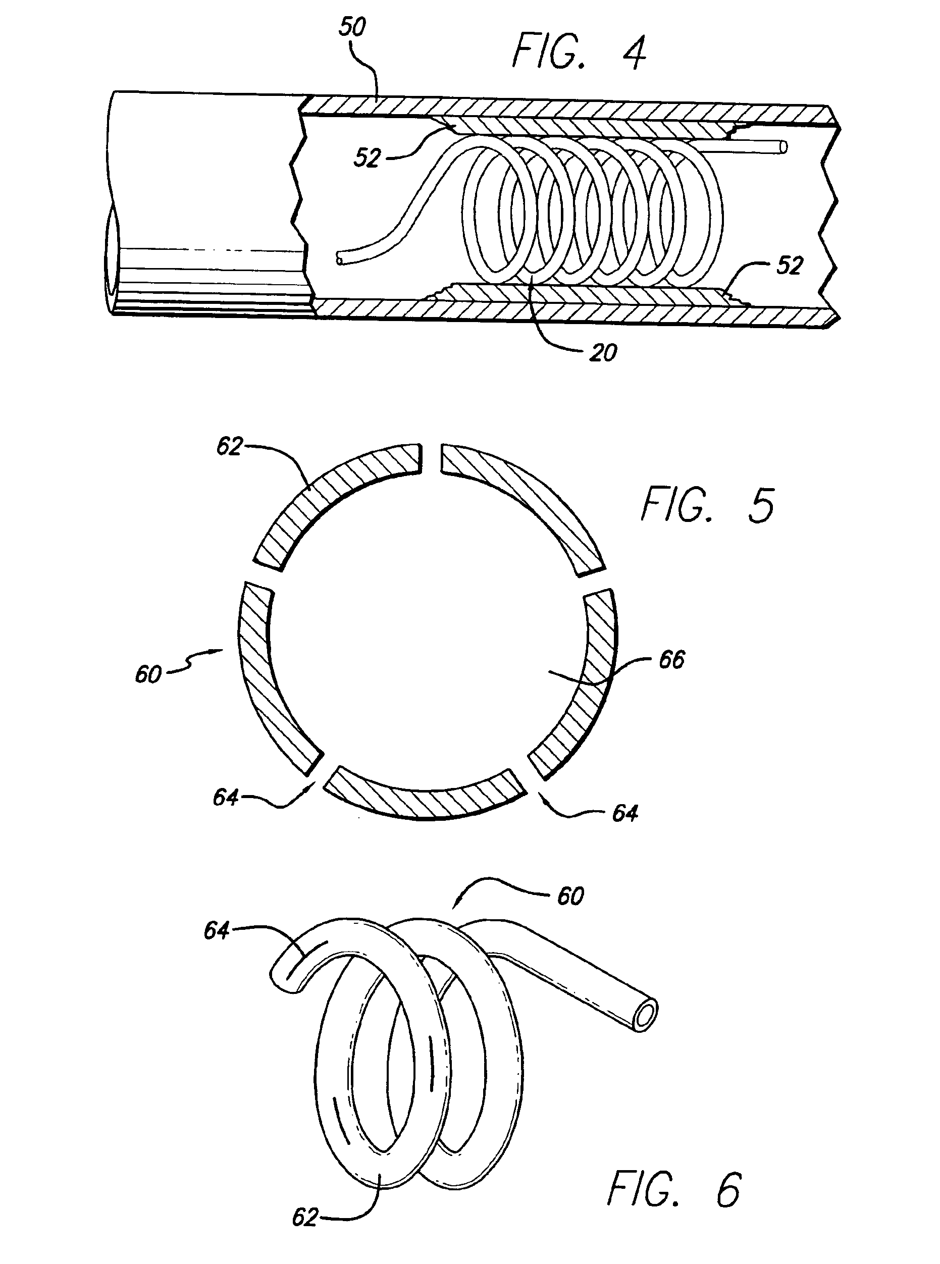
[0034]FIG. 5 depicts the invention. In this embodiment, the hollow stent 60 has only one fluid pathway 66, an inlet without an outlet, and is used to deliver drugs to affected areas. Once the stent 60 is inserted into place and is in its enlarged configuration, drugs are delivered through the catheter to the stent 60. Stent 60 can be constructed in various ways to facilitate the delivery of drugs. In one case, as shown in FIG. 6, the stent 60 is constructed with regions or segments that have pores 64 to allow drug seepage from the tubing 62. Alternatively, continuously porous metal, porous plastic, or a combination of metal and plastic can be used. The perforations 64 or slits in the stent to facilitate drug delivery must be of sufficiently small size to allow the passage of the drug through the entire length of the stent so that all areas can be treated. It will be apparent that pore size can control the rate at which the drug is dispensed. It is possible to cover the pores 64 with...

third embodiment

[0035]the invention, FIG. 7, has a hollow stent 70 containing a single fluid pathway. The tubing 72 can be made of any of the materials discussed above, but in this embodiment, the stent 70 has an inlet path 78 that carries the fluid to the distal end 74 of stent 70 where it then runs through the coils. In this embodiment, a valve 80 connects the stent 70 to catheter 30. FIG. 8 a cross-sectional view of valve 80. The pressure from the liquid sent through the catheter causes the gate 82 of valve 80 to open to allow the fluid into the inlet path 78. The pressure that forces the opening of gate 82 causes the simultaneous opening of gate 84, allowing the fluid that is circulated through the stent 70 to exit through pathway 36 of catheter 30. The fluid entering and exiting through catheter 30 must also go through a check ball valve assembly similar to the one shown in FIG. 2. Again, flaps or other “one way” valve mechanisms can be applied. After all incoming fluid has been delivered to t...

fourth embodiment

[0036]In a fourth embodiment, a hollow coiled stent 90 is formed from polytetrafluoroethylene (PTFE) 92. In FIG. 9, a perspective view of this embodiment can be seen. The stent 90 consists of a support wire 94 over which PTFE 92 is fitted. The pliable structure resulting is then formed into a coiled stent. The PTFE 92 is fitted around the wire 94 so that there is sufficient room to allow the passage of fluid. FIG. 10 shows a cross-sectional view of stent 90, illustrating the pathway 96 created around the support wire 94 to allow the passage of fluid. In this embodiment, stretched expanded PTFE can be used to create a porous stent to facilitate the delivery of drugs. The wire 94 can also be hollow (passageway 95) so that the stent 90 can simultaneously deliver drugs and radioactive fluid or temperature regulating fluid.


PUM


Abstract

An endoluminal stent contains a hollow passageway for the circulation of heated and/or cryogenic fluids to recapture a previously implanted shape memory stent. The hollow passageway stent can have one or a plurality of passageways and is configured in a tubular shape with numerous coils, providing an empty tubular lumen through the center of the stent to allow blood flow. The stent is connected to a removable catheter that conducts fluid to the stent. Fluid flow may be regulated by valves incorporated in either the stent and/or the catheter.

Description

CROSS-REFERENCE TO RELATED APPLICATIONS[0001]This application is a division of application Ser. No. 09 / 975,743, filed Oct. 11, 2001, now U.S. Pat. No. 6,623,519, which is a division of application Ser. No. 09 / 321,496, filed May 27, 1999, now U.S. Pat. No. 6,358,276, which claims the benefit of U.S. Provisional Application No. 60 / 105,768, filed Sep. 30, 1998. This application expressly incorporates by reference the entirety of each of the above-mentioned applications as if fully set forth herein.BACKGROUND OF THE INVENTION[0002]The present invention relates generally to endoluminal devices, and more particularly to stents.[0003]Stents and similar endoluminal devices have been used to expand a constricted vessel to maintain an open passageway through the vessel in many medical situations, for example, following angioplasty of a coronary artery. In these situations, stents are useful to prevent restenosis of the dilated vessel through proliferation of vascular tissues. Stents can also ...

Claims


Application Information

Patent Timeline
Patent Type & Authority Patents(United States)
IPC IPC(8): A61F2/06A61F2/00A61M31/00A61F2/82A61F2/88A61M25/00
CPCA61F2/82A61F2/88A61F2250/0067A61F2210/0042
Inventor EDWIN, TARUN J.BANAS, CHRISTOPHER E.
Owner BARD PERIPHERAL VASCULAR
Why Eureka
Try Eureka