Dynamic pulse plating for high aspect ratio features

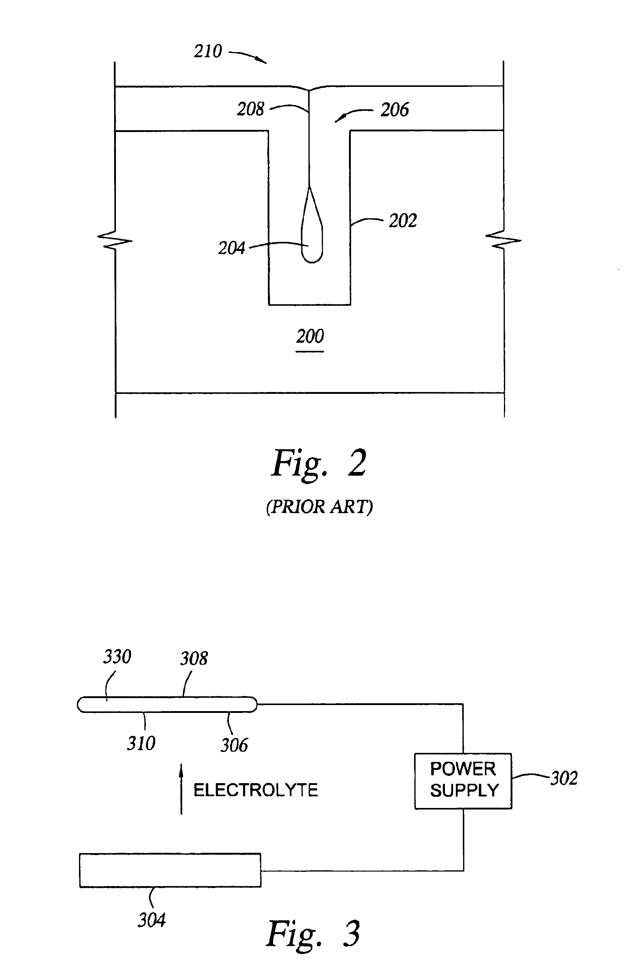
a technology of dynamic pulse plating and feature, applied in the field of electrochemical deposition of metal, can solve the problems of increasing the current density of the feature, void formation in the conductor, and many conventional deposition processes have difficulty filling structures, etc., and achieve the effect of high aspect ratio features

Inactive Publication Date: 2005-04-19
APPLIED MATERIALS INC
View PDF5 Cites 43 Cited by
  • Summary
  • Abstract
  • Description
  • Claims
  • Application Information

AI Technical Summary

Problems solved by technology

Many conventional deposition processes have difficulty filling structures where the aspect ratio exceeds 4:1, and particularly where the aspect ratio exceeds 10:1.
Additionally, as the feature widths decrease, the device current remains constant or increases, which results in an increased current density in the feature.
However, aluminum has a higher electrical resistivity than other more conductive metals such as copper, and aluminum also can suffer from electromigration leading to the formation of voids in the conductor.
Despite the desirability of using copper for semiconductor device fabrication, choices of fabrication methods for depositing copper into very high aspect ratio features, such as 4:1, having 0.35 μm (or less) wide vias are limited.
As a result of these process limitations, plating, which had previously been limited to the fabrication of lines on circuit boards, is just now being used to fill vias and contacts on semiconductor devices.
One particular problem encountered in existing electroplating processes is that these electroplating processes have not been able to provide void-free or seam-free fill of high aspect ratio structures. FIG. 2 illustrates a typical deposition result of a high aspect ratio feature 202 on a substrate 200 wherein the mouth / opening 206 of the structure 202 closes off due to overhang or excess deposition of copper at the mouth / opening 206 of the structure 202 also known as crowning.
The crowning is accelerated by an increase of the current densities during electroplating, thereby causing even larger voids.
It has been observed that voids are also formed in the interconnect features due to grain mismatches from the deposition growth.
Furthermore, the presence of the seam 208 may result in void formation during subsequent processing such as substrate annealing.

Method used


Image

  • Dynamic pulse plating for high aspect ratio features
  • Dynamic pulse plating for high aspect ratio features
  • Dynamic pulse plating for high aspect ratio features

Examples


example

[0048]An example is given below of copper electroplating according to one embodiment of the invention on a substrate having high aspect ratio interconnect features. Prior to electroplating, a barrier layer comprising about 250 Å of tantalum nitride is deposited by physical vapor deposition over the substrate using processing parameters that are known in the art. Preferably, the barrier layer is deposited using a Vectra IMP™ chamber from Applied Materials, Inc., Santa Clara, Calif.

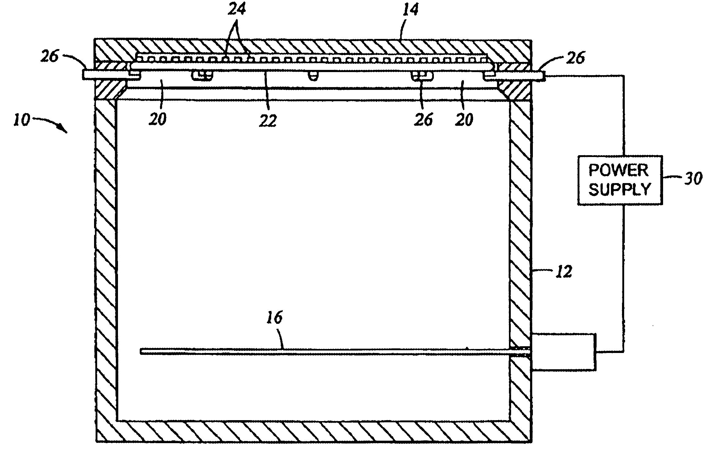
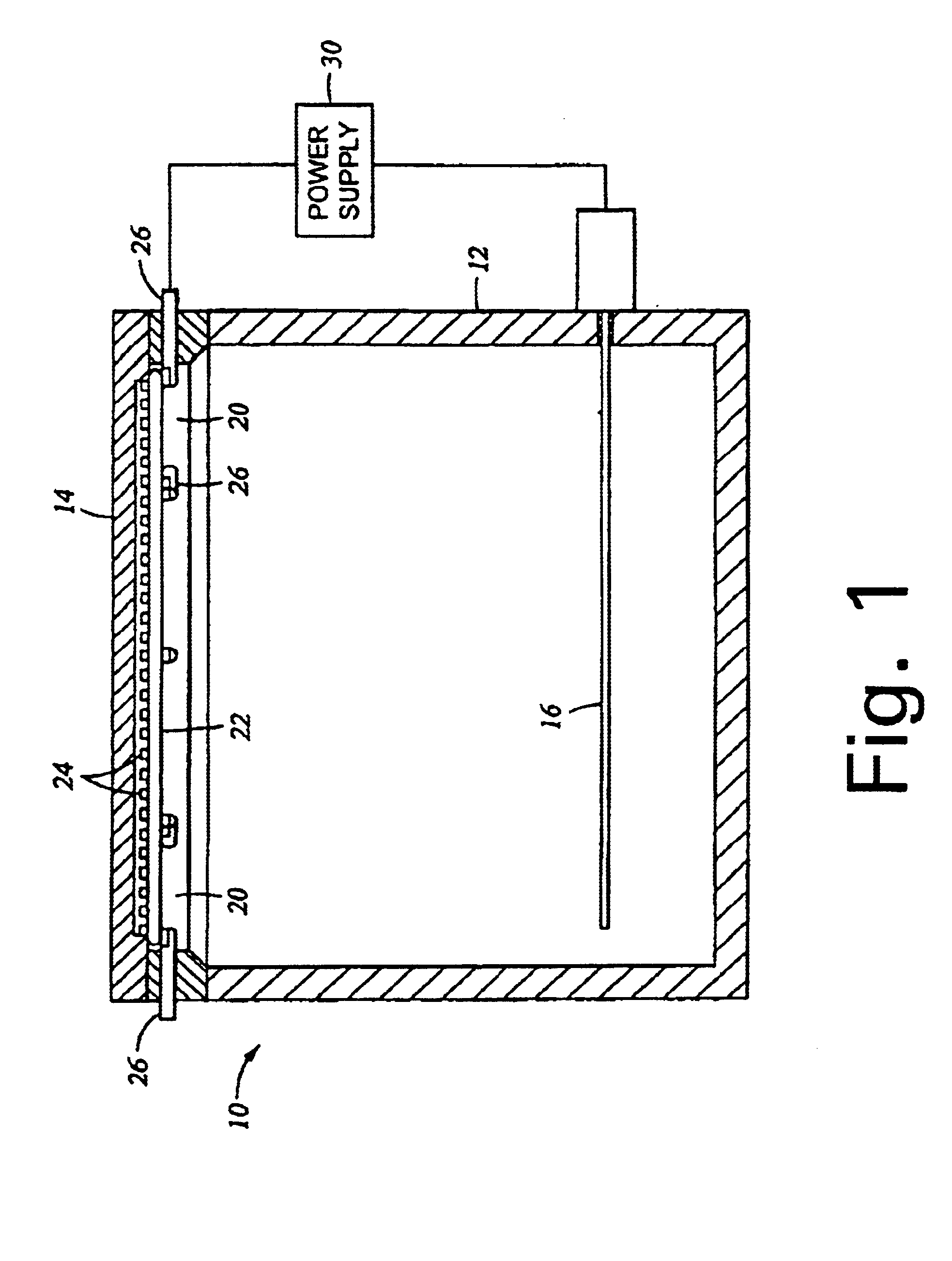
[0049]A copper seed layer having a thickness of about 2000 Å is formed on the barrier layer, using, for example, known processing parameters for physical vapor deposition. The substrate is then transferred to an electroplating cell, e.g., a Millenia™ ECP system, available from Applied Materials, Inc., for copper electroplating.

[0050]In this embodiment, the electroplating bath comprises 0.85 M copper sulphate, appropriate additives (suppressers and accelerators) and chloride ions at about 60 to about 70 ppm,...


PUM

PropertyMeasurementUnit
timeaaaaaaaaaa
timeaaaaaaaaaa
time durationaaaaaaaaaa

Abstract

A method for depositing a metal on a substrate is provided. The metal is deposited by sequentially applying a electrodeposition pulse followed by an electrodissolution pulse to the substrate. After each electrodissolution pulse an before the next electrodeposition pulse there is provided at least one time interval of zero electrical voltage or current, also known as an “off-time”, between the pulses. The first two electrodeposition pulses should preferably have the same time durations. Thereafter, the time durations of subsequent electrodeposition pulses are gradually decreased to provide a void-free and seam-free deposition of metal in high aspect ratio features.

Description

BACKGROUND OF THE DISCLOSURE[0001]1. Field of the Invention[0002]The present invention relates to electrochemical deposition of a metal.[0003]2. Description of the Related Art[0004]Sub-quarter micron, multi-level metallization is one of the key technologies for the next generation of ultra large scale integration (ULSI). The multilevel interconnects that lie at the heart of this technology require planarization of interconnect features formed in high aspect ratio apertures, including contacts, vias, lines and other features. Reliable formation of these interconnect features is very important to the success of ULSI and to the continued effort to increase circuit density and quality on individual substrates and die.[0005]As circuit densities increase, the widths of vias, contacts and other features, as well as the dielectric materials between them, decrease to less than 250 nanometers, whereas the thickness of the dielectric layers remains substantially constant, with the result that ...

Claims


Application Information

Patent Timeline
Patent Type & Authority Patents(United States)
IPC IPC(8): C25D5/18C25D7/12C25D5/00
CPCC25D7/123C25D5/18
Inventor HEY, H. PETER W.DORDI, YEZDI
Owner APPLIED MATERIALS INC
Why Eureka
Try Eureka