

Contoured battery for implantable medical devices and method of manufacture
- Summary
- Abstract
- Description
- Claims
- Application Information
AI Technical Summary
Benefits of technology
Problems solved by technology
Method used
Image

Examples
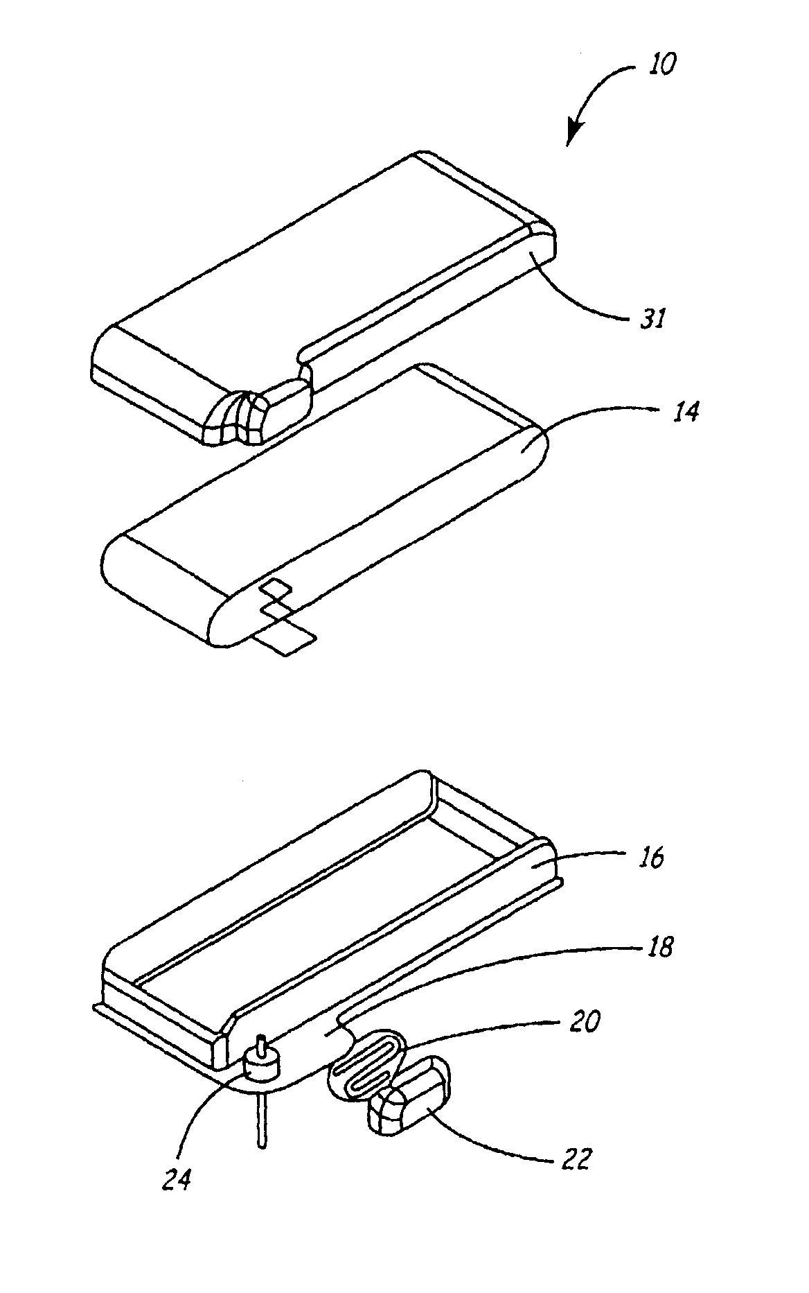
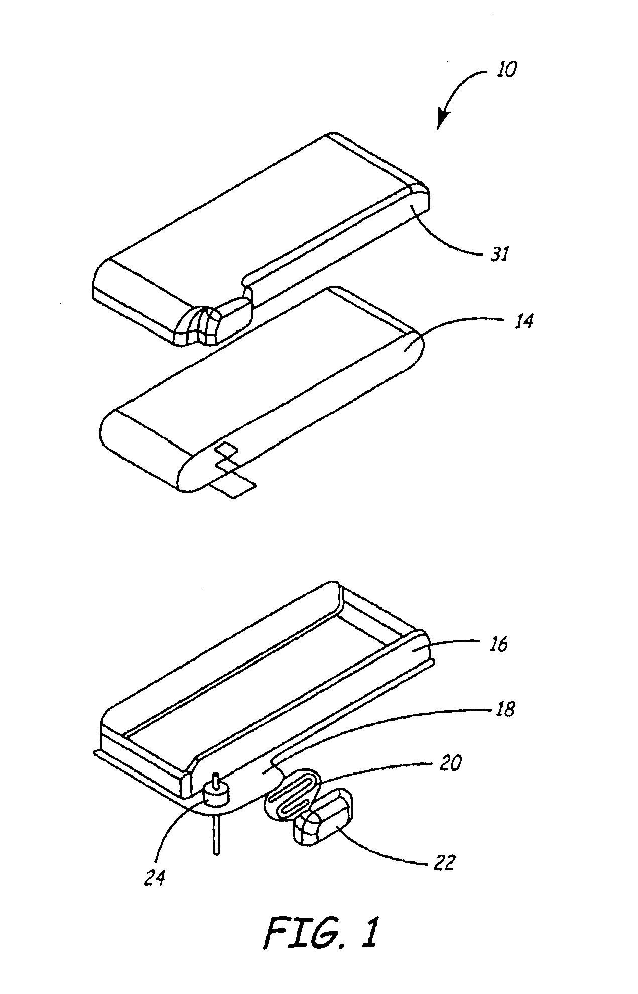
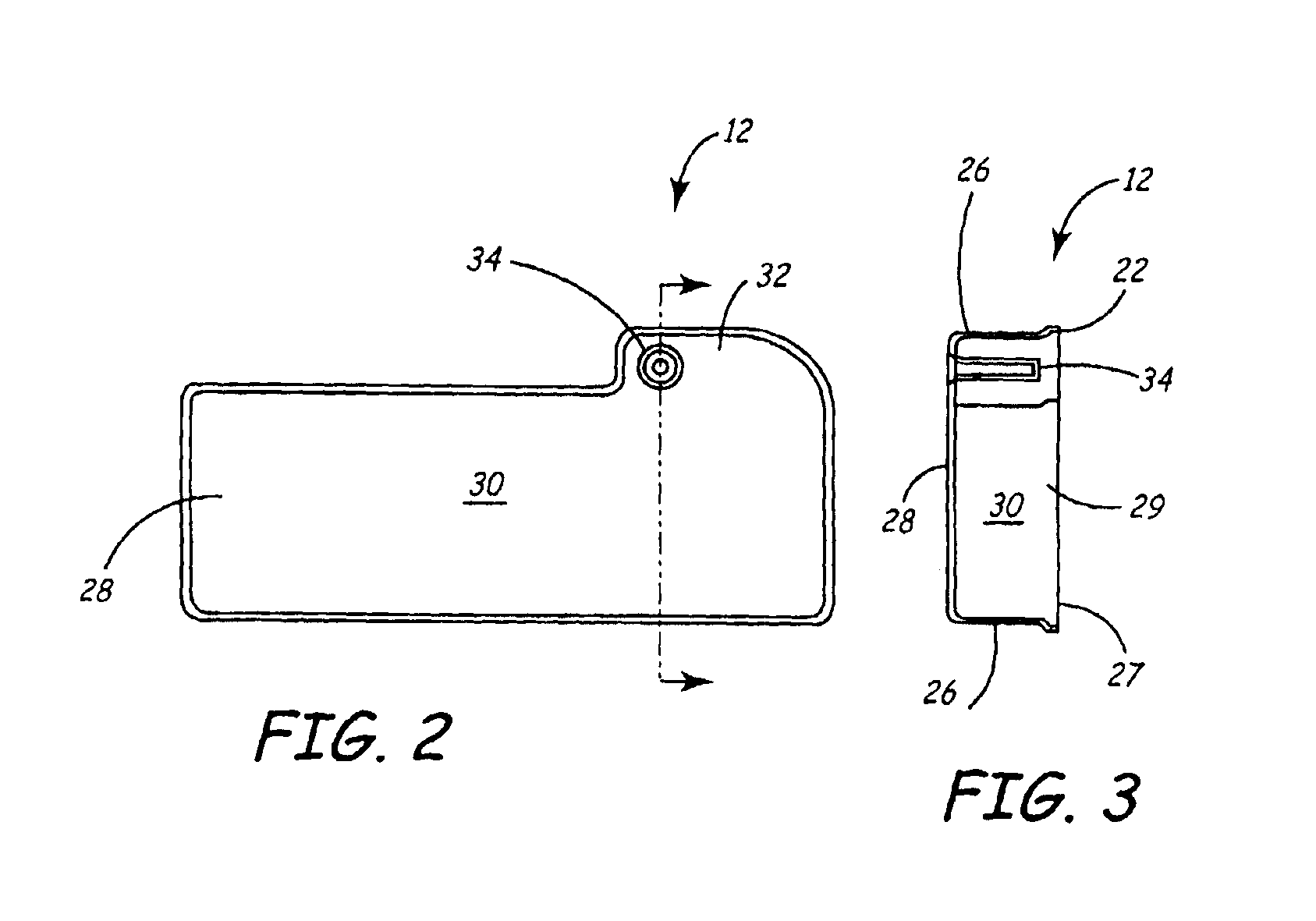
case 12
[0039]Battery case 12 is preferably made of a medical grade titanium, however, it is contemplated that battery case 12 could be made of almost any type of material, such as aluminum and stainless steel, as long as the material is compatible with the battery's chemistry in order to prevent corrosion. Further, it is contemplated that shallow battery case 12 could be manufactured from most any process including but not limited to machining, casting, milling, stamping, thermoforming, vacuum forming, injection molding and using so-called rapid prototyping techniques (e.g., such as using an SLA) and the like. However, case 12 is preferably manufactured using a shallow drawing process. Headspace 32 houses insulators and connector tabs, which transfer electrical energy from electrode assembly 14 to the implantable medical device circuitry and will be discussed in more detail below. However, as shown in FIG. 2, a significant amount of headspace is reduced from prior battery assemblies such a...
PUM
| Property | Measurement | Unit |
|---|---|---|
| Thermal properties | aaaaa | aaaaa |
| Opacity | aaaaa | aaaaa |
Abstract
Description
Claims
Application Information