Phase angle controlled stationary elements for long wavelength electromagnetic radiation

a technology of electromagnetic radiation and phase angle control, which is applied in the direction of mechanical recording, relays, instruments, etc., can solve the problems of cost, power and functionality, expensive phase shifters, and discrete electronic components (e.g. capacitors and inductors) losing their functionality,

Inactive Publication Date: 2005-04-19
ENERGY CONVERSION DEVICES INC
View PDF8 Cites 18 Cited by
  • Summary
  • Abstract
  • Description
  • Claims
  • Application Information

AI Technical Summary

Benefits of technology

[0015]In a further embodiment, an element is provided for correcting or removing distor...

Problems solved by technology

Although conventional rf systems are generally compatible with millimeter wave applications, problems associated with cost, power and functionality arise, especially in the sub-millimeter range.
Cost issues stem from the expensive phase shifters needed for the directional transmission or reception of rf radiation.
Power issues arise in the context of active phase arrays, which utilize solid-state devices.
Moreover, at sufficiently high frequencies, discrete electronic component...

Method used


Image

  • Phase angle controlled stationary elements for long wavelength electromagnetic radiation
  • Phase angle controlled stationary elements for long wavelength electromagnetic radiation
  • Phase angle controlled stationary elements for long wavelength electromagnetic radiation

Examples


example 1

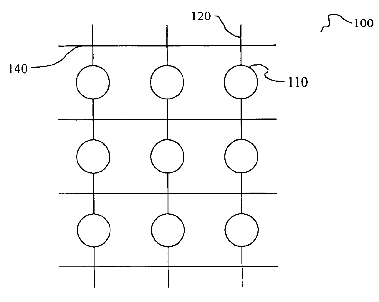
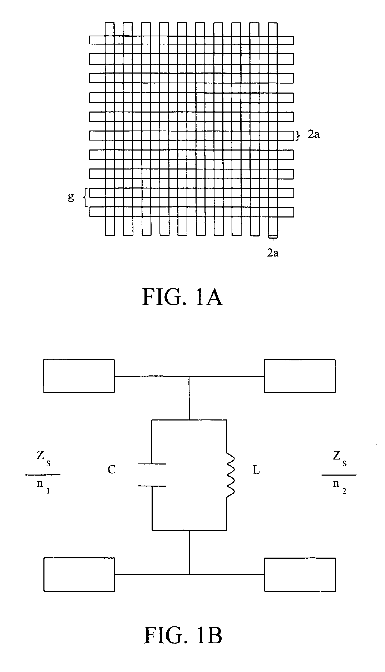
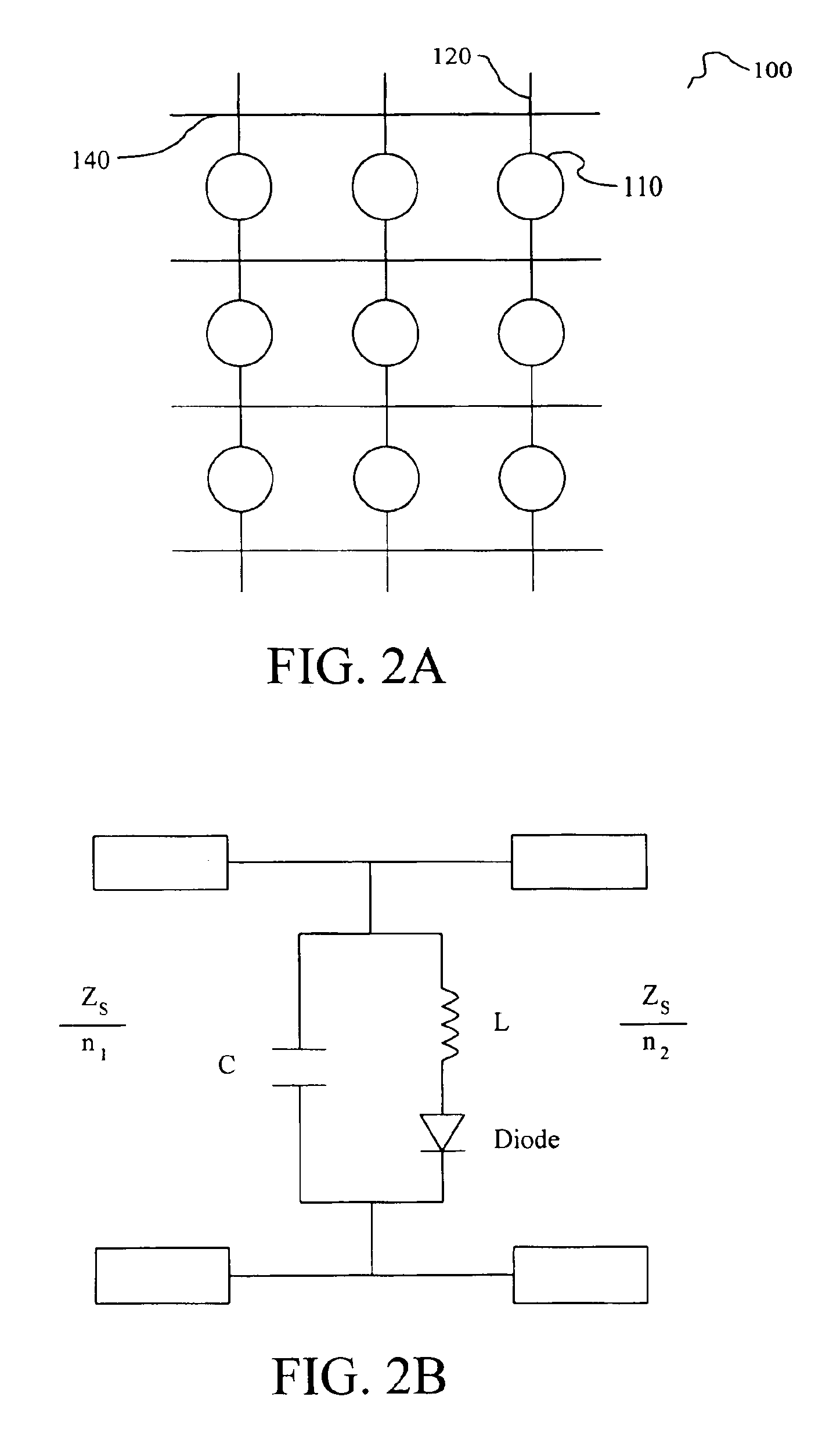
[0111]In this example, a stationary element without beam steering is described. The element is schematically depicted in FIG. 5A. The element includes a square grid 200 with grid period g that includes horizontal conductive strips 240 and vertical conductive strips 220 that include conductive segments 230, active regions 210 that include a volume of chalcogenide material, and junctions 250 between chalcogenide regions 210 and conductive segments 230. The active chalcogenide regions 210 are connected in series with the conductive segments 230 to form vertical strips 220. The active chalcogenide regions 210 may also be said to interconnect conductive segments 230. In this embodiment, each active region 210 interconnects two conductive segments 230. Although the active regions 210 are schematically depicted as circles, the shape of the active regions, or volume of chalcogenide material therein, is not limited to a circular shape. Chalcogenide regions having any shape are within the sco...

example 2

[0119]In this example, representative elements with beam steering capability are described. Specifically, elements with square grids similar to that described in EXAMPLE 1 are presented that provide beam steering of an incident electromagnetic beam. As discussed hereinabove and in co-pending U.S. patent application Ser. No. 10 / 226,828, beam steering may be achieved with an element that incorporates a continuous or discrete phase taper. In some embodiments of the instant example, a phase taper is achieved through the formation of a crystallinity gradient in the volumes of chalcogenide material distributed in one or more directions across the active regions of an element. In other embodiments, a phase taper is achieved through the formation of a crystallinity gradient over a series of domains, each of which comprises a plurality of sub-wavelength active chalcogenide regions. Non-uniformity of the structural state of the active chalcogenide regions in one or more directions across a gr...

example 3

[0126]In this example, additional elements with beam steering capability are described. More specifically, elements capable of focusing or defocusing incident electromagnetic radiation in reflection or transmission mode are described. Focusing and defocusing effects may be achieved by establishing a crystallinity gradient, over individual active chalcogenide regions or domains comprising a plurality of sub-wavelength chalcogenide regions, in which the variation of fractional crystallinity is non-uniform in one or more directions across the chalcogenide regions or domains of an element. A crystallinity gradient in a particular direction, for example, having portions over which the fractional crystallinity increases and other portions over which the fractional crystallinity decreases may provide focusing or defocusing.

[0127]FIG. 9 shows an embodiment of an element that can be used to symmetrically focus or defocus an incident electromagnetic beam in one direction. The element includes...


PUM


Abstract

An element for reflecting, transmitting, focusing, defocusing or wavefront correction of electromagnetic radiation in the terahertz frequency range. The elements include a grid of conductive strips including active regions comprising a chalcogenide phase change material. The chalcogenide material can be in an amorphous, crystalline or partially crystalline state. The dispersive characteristics of the grid (e.g. impedance, admittance, capacitance, inductance) influence one or more of the reflection, transmission, state of focusing or wavefront characteristics of incident electromagnetic radiation through the action of a stored phase taper formed by establishing a crystallinity gradient over a series of active chalcogenide regions or domains in one or more directions of the element. The dispersive characteristics of the grid are determined by the structural states of the active chalcogenide regions contained therein and are reconfigurable through transformations of one or more chalcogenide regions from one structural state to another by providing energy to the chalcogenide material. In a preferred embodiment, the individual active chalcogenide regions are much smaller than the operating wavelength of the element so that a plurality of active chalcogenide regions is included in wavelength scale domains. In these embodiments, crystallinity gradients may be formed through monotonic increases or decreases in the domain average fractional crystallinity in one or more directions of an element where no particular requirement on the fractional crystallinity of individual active regions need be imposed. In these embodiments, the domain fractional crystallinity is a statistical average over the individual chalcogenide regions contained therein and phase tapers may be achieved in multistate or binary mode. The element may be free-standing, supported on a dielectric substrate or interposed between two or more dielectric materials.

Description

CROSS-REFERENCE TO RELATED APPLICATIONS[0001]The instant invention is a continuation in part of co-pending U.S. patent application Ser. No. 10 / 226,828, entitled “Phase Angle Controlled Stationary Elements for Wavefront Engineering of Electromagnetic Radiation” and filed on Aug. 23, 2002, now U.S. Pat. No. 6,768,666 B2; the disclosure of which is hereby incorporated by reference.FIELD OF INVENTION[0002]This invention relates to devices for controlling the direction of propagation and degree of focusing of electromagnetic radiation. More particularly, this invention relates to stationary elements that provide control over the reflection, transmission, focusing, and defocusing of long wavelength electromagnetic radiation. Most particularly, this invention relates to reconfigurable elements for modifying the phase of incident electromagnetic radiation in the terahertz frequency range of the electromagnetic spectrum.BACKGROUND OF THE INVENTION[0003]Interest in terahertz frequency systems...

Claims


Application Information

Patent Timeline
IPC IPC(8): G02F1/29G02F1/01G02B6/32G01NG02B6/42G02B26/06G02F1/31G11C13/00H01H51/22H01Q15/00H01Q23/00
CPCG02F1/292H01Q15/002H01Q23/00G02F1/0126G02F2203/18G02F2203/13H05K9/00
Inventor TSU, DAVIDMILLER, ROBERT O.
Owner ENERGY CONVERSION DEVICES INC
Why Eureka
Try Eureka