

Optical recording medium with high density track pitch and optical disk device for recording and playback of the same
a recording medium and high density technology, applied in the field of optical recording mediums, can solve the problems of difficult to achieve uniform quality of playback signals at lands and grooves, difficult to propagate electromagnetic waves, and uneven optimum output at the time of recording, so as to prevent crosswriting and ensure easy compatibility. the effect of uniformity and the prevention of playback signals
- Summary
- Abstract
- Description
- Claims
- Application Information
AI Technical Summary
Benefits of technology
Problems solved by technology
Method used
Image

Examples
example 1
[0119]The jitter and push-pull signal of a measured track in an optical disk of the above embodiment having a track pitch of 0.32 μm when using the 1-7RPP scheme as the modulation scheme, making the shortest mark length 0.16 μm, overwriting the track measured 100 times, then overwriting the adjoining track 100 times were measured. How these measured values changed when changing the depth of the recessed portions with respect to the projecting portions of the disk substrate was investigated.
[0120]FIG. 9 shows the results of the above measurement. In the figure, the black dots show the values of jitter, while the white dots show the values of the push-pull signal.
[0121]To maintain stable tracking, the push-pull signal has to be made at least 0.25. To satisfy this, it is necessary that the depth of the recessed portions with respect to the projecting portions of the disk substrate be made at least 19 nm.
[0122]On the other hand, for system margin, jitter has to be made not more than 8.5...
example 2
[0124]FIG. 10 is a plan view of an example of wobble in an optical disk of the above embodiment.
[0125]If the depth of the recessed portions with respect to the projecting portions of the disk substrate is set to the range determined in Example 1, the modulation degree of the bit signal when forming the address information as bits becomes less than 20% or insufficient, so a wobble is formed in the grooves to incorporate the address information.
[0126]The areas between one groove G and another groove G become the lands L. A wobble WB is formed in the grooves G. This shows that, therefore, the widths of the lands L do not become constant.
[0127]When using as units the channel clock T of the optical disk device, setting the length LWB of one cycle of the wobble WB at 69T, and making T=0.08 μm, LWB becomes 5.52 μm.
example 3
[0128]The wobble signal is determined by its amplitude. As shown in FIG. 10, the amplitude AWB of the wobble WB is the difference between the center position of the groove in the case of no wobble and the center position of the groove when wobbled the maximum in one direction.
[0129]FIG. 11 shows the C / N ratio of the wobble signal when changing the wobble amplitude. In general, the C / N ratio of a wobble signal has to be at least 40 dB, so the amplitude of the wobble has to be at least ±8 nm.
[0130]On the other hand, the upper limit of the wobble amplitude is determined by the amount of leakage of wobble from the adjoining tracks. In experiments, address error occurred when more than ±12 nm.
[0131]From the above results, the amplitude AWB of the wobble is set to a range of ±8 to 12 nm.
PUM
| Property | Measurement | Unit |
|---|---|---|
| wavelength | aaaaa | aaaaa |
| depth | aaaaa | aaaaa |
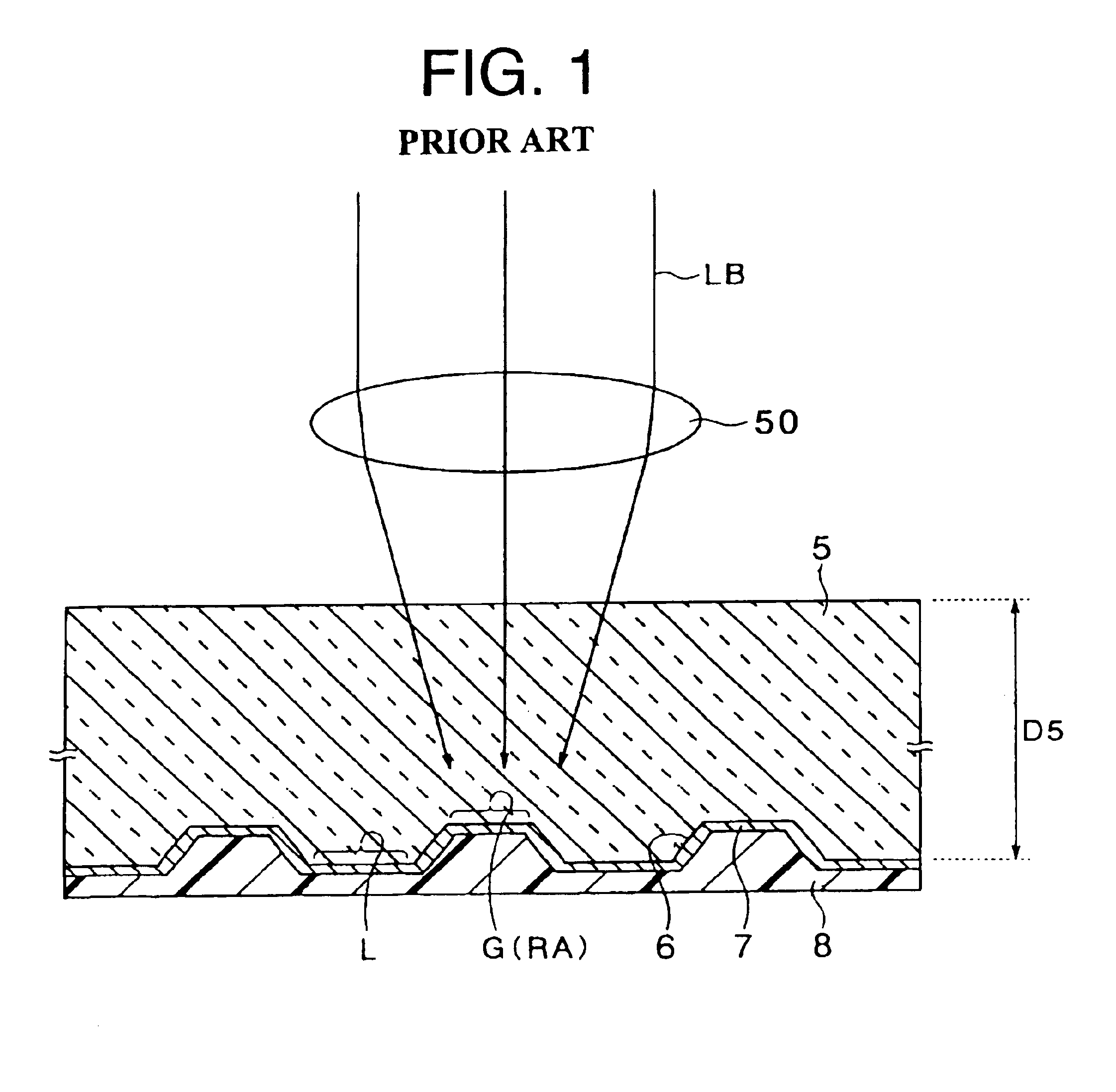
| thickness D5 | aaaaa | aaaaa |
Abstract
Description
Claims
Application Information