Methods and apparatus for generating gas turbine engine thrust with a pulse detonation thrust augmenter

a gas turbine engine and pulse detonation technology, which is applied in the direction of intermittent jet plants, marine propulsion, vessel construction, etc., can solve the problems of limited performance of such systems and limited thrust increase of the generator, and achieve the effect of increasing the temperature and pressure of the engin

Inactive Publication Date: 2005-04-26
GENERAL ELECTRIC CO
View PDF17 Cites 38 Cited by
  • Summary
  • Abstract
  • Description
  • Claims
  • Application Information

AI Technical Summary

Benefits of technology

[0004]In one aspect, a method for generating thrust from a gas turbine engine using a pulse detonation system is provided. The engine includes an inlet portion and an exhaust portion, and the pulse detonation system includes an pulse detonation augmentor including a multi-staged predetonator. The method comprises supplying a less than stoichiometric fuel / air mixture to the pulse detonation system during a first operating stage, detonating the fuel / air mixture with the predetonator to increase the temperature and pressure within the engine and to generate engine thrust, and supplying additional fuel and air to the predetonator during a second operating stage.

Problems solved by technology

However, augmentors are limited to a level of thrust increase by stoichiometry, and as a result, for an engine to operate efficiently over a wide range of operating flight speeds, several different combustion systems may be required.
However, the performance of such systems is generally limited because of inherent deficiencies that may exist because the deflagration process consumes energy without the benefit of detonation, which occurs only on the remainder of any unconsumed fuel.

Method used


Image

  • Methods and apparatus for generating gas turbine engine thrust with a pulse detonation thrust augmenter
  • Methods and apparatus for generating gas turbine engine thrust with a pulse detonation thrust augmenter
  • Methods and apparatus for generating gas turbine engine thrust with a pulse detonation thrust augmenter

Examples


Embodiment Construction

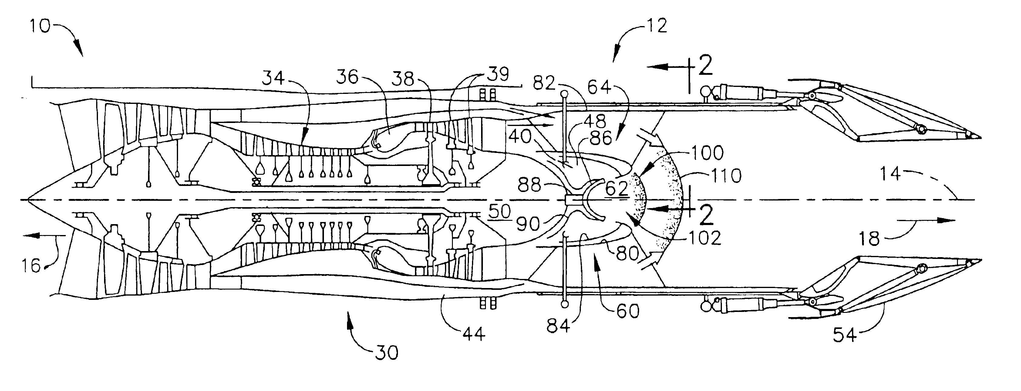
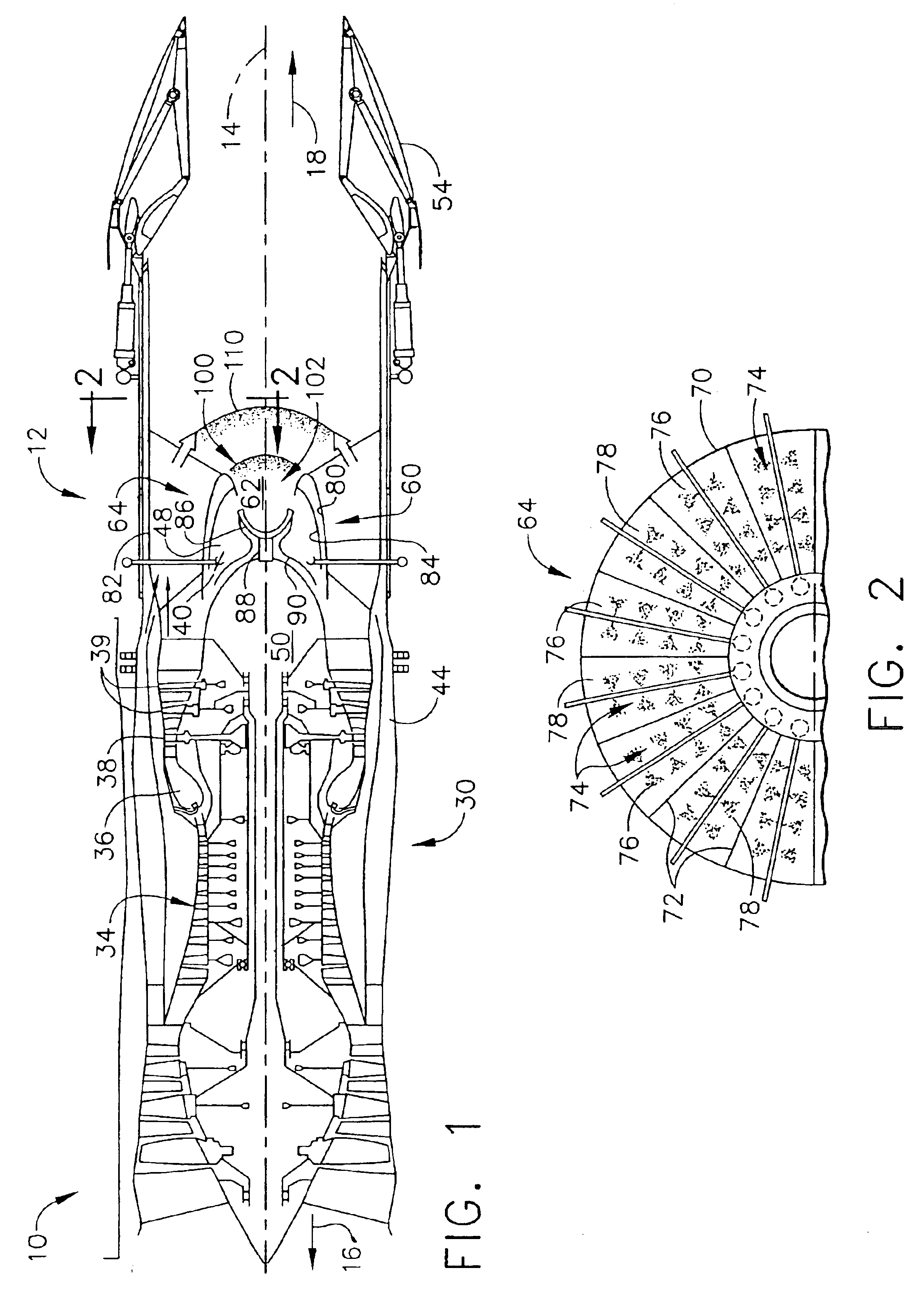
[0010]FIG. 1 is a cross-sectional side view of a gas turbine engine 10 including a pulse detonation system 12. FIG. 2 is a cross sectional view of a portion of pulse detonation system 12 taken along lines 2—2 shown in FIG. 1. In one embodiment, engine 10 is an F110 / 129 engine available from General Electric Aircraft Engines, Cincinnati, Ohio. Engine 10 has a generally longitudinally extending axis or centerline 14 extending in a forward direction 16 and an aft direction 18. Engine 10 includes a core engine 30 which includes a high pressure compressor 34, a combustor 36, a high pressure turbine 38, and a power turbine or a low pressure turbine 39 all arranged in a serial, axial flow relationship. Engine 10 also includes a bypass duct 44 that surrounds core engine 30, and enables fluid flow to be routed downstream from core engine 30 rather than through core engine 30. In an alternative embodiment, engine 10 includes a core fan assembly (not shown). An annular centerbody 50 extends do...


PUM


Abstract

A method enables thrust to be generated from a gas turbine engine using a pulse detonation system is provided. The engine includes an inlet portion and an exhaust portion, and the pulse detonation system includes a multi-staged pulse detonation augmentor including predetonator. The method comprises supplying a less than stoichiometric fuel/air mixture to the pulse detonation system during a first operating stage, detonating the fuel/air mixture with the predetonator to increase the temperature and pressure within the engine and to generate engine thrust, and supplying additional fuel and air to the pulse detonation system during a second operating stage.

Description

BACKGROUND OF THE INVENTION[0001]This invention relates to gas turbine engines, and more particularly, to a pulse detonation system for a gas turbine engine.[0002]Variable cycle turbofan ramjet engines may be used to provide aircraft flight speeds between low subsonic Mach numbers to high supersonic Mach numbers of about Mach 6. Known engines, as described in U.S. Pat. No. 5,694,768, include a core engine system and a dual mode augmentor. The dual mode augmentor provides additional beat to exhaust airflow exiting the core engine system to increase engine thrust. The core engine system provides power to drive a fan assembly and typically includes in serial, axial flow relationship, a compressor, a combustor, a high pressure turbine, and a low pressure turbine. The dual mode augmentor is positioned downstream from the core engine and receives air from the core engine and a bypass duct surrounding the core engine. However, augmentors are limited to a level of thrust increase by stoichi...

Claims


Application Information

Patent Timeline
Patent Type & Authority Patents(United States)
IPC IPC(8): F02K7/06F02K7/075F02K3/08F02K3/075F02K7/00F02K3/00F02K1/00F02K7/04F02C5/10F23R7/00
CPCF02K3/075F02K7/075F02K7/06F02K3/08
Inventor KOSHOFFER, JOHN MICHAEL
Owner GENERAL ELECTRIC CO
Why Eureka
Try Eureka