Quilting method and apparatus

a technology of quilting and sewing machine, applied in the direction of sewing machine control devices, thin material processing, textiles and paper, etc., can solve the problems of requiring significant user skill, labor-intensive hand quilting process, and months of effort, and achieve free-motion quilting with a conventional sewing machin

Active Publication Date: 2005-04-26
BERNINA SEWING MACHINE
View PDF24 Cites 65 Cited by
  • Summary
  • Abstract
  • Description
  • Claims
  • Application Information

AI Technical Summary

Benefits of technology

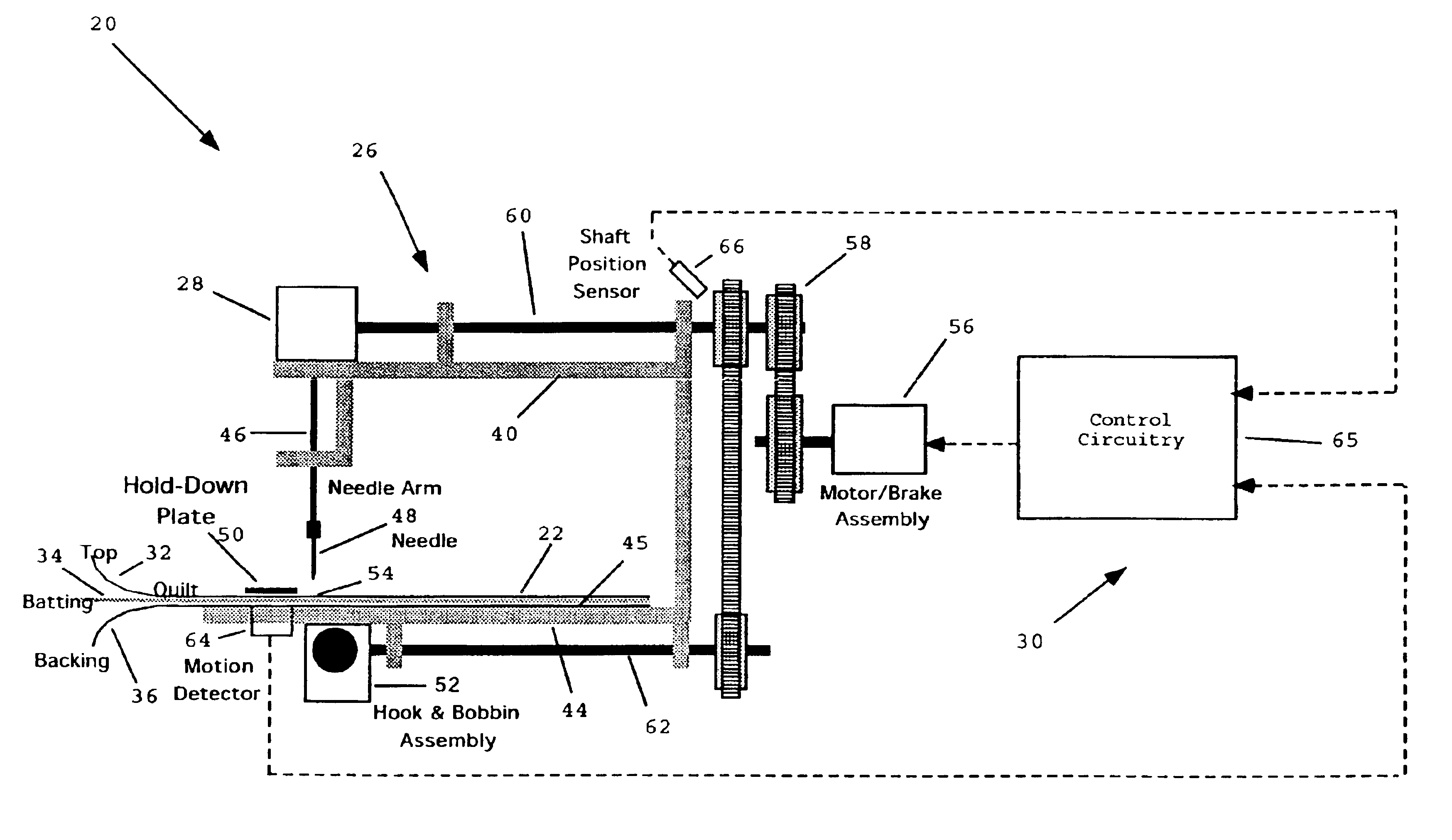
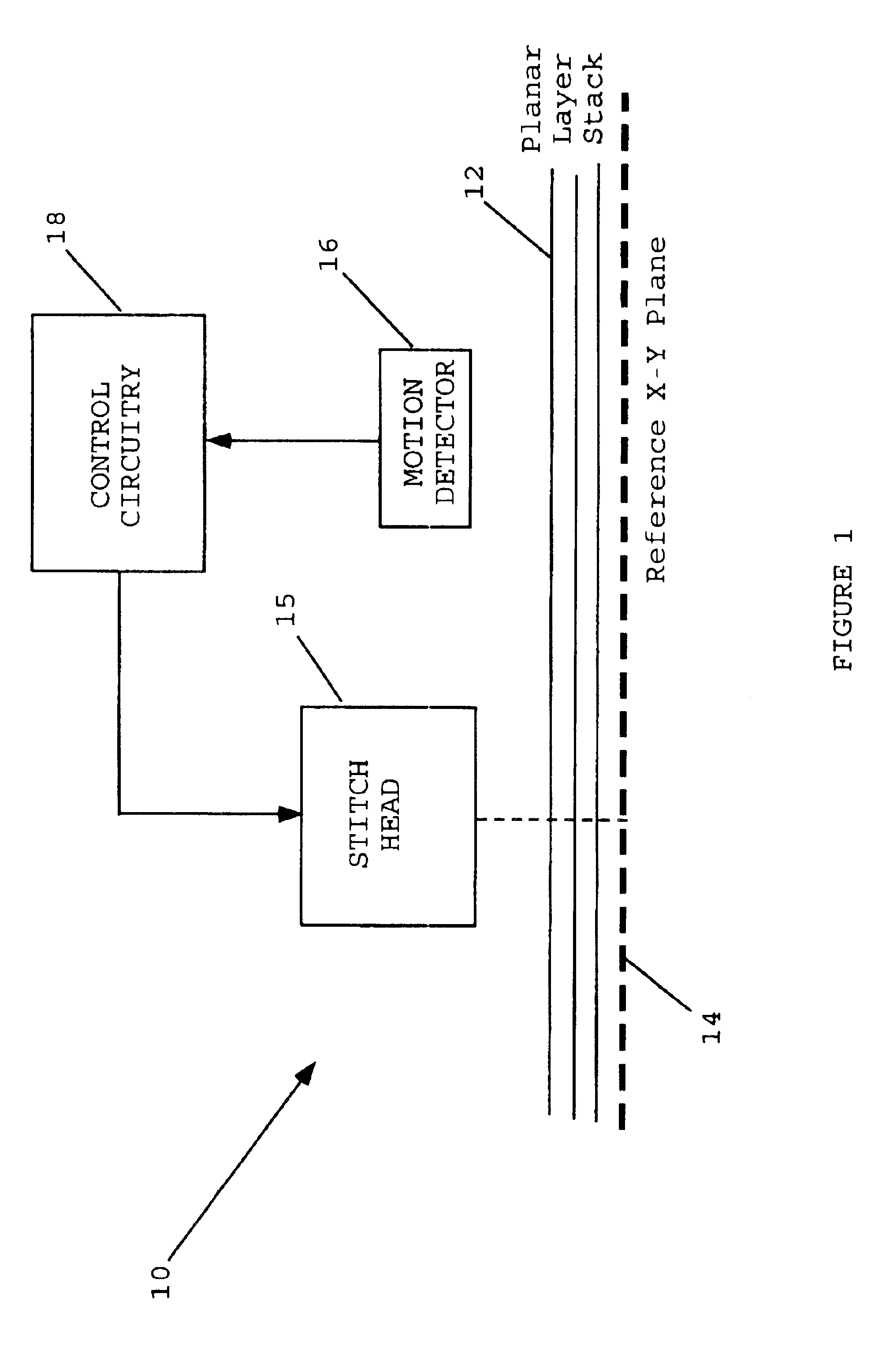
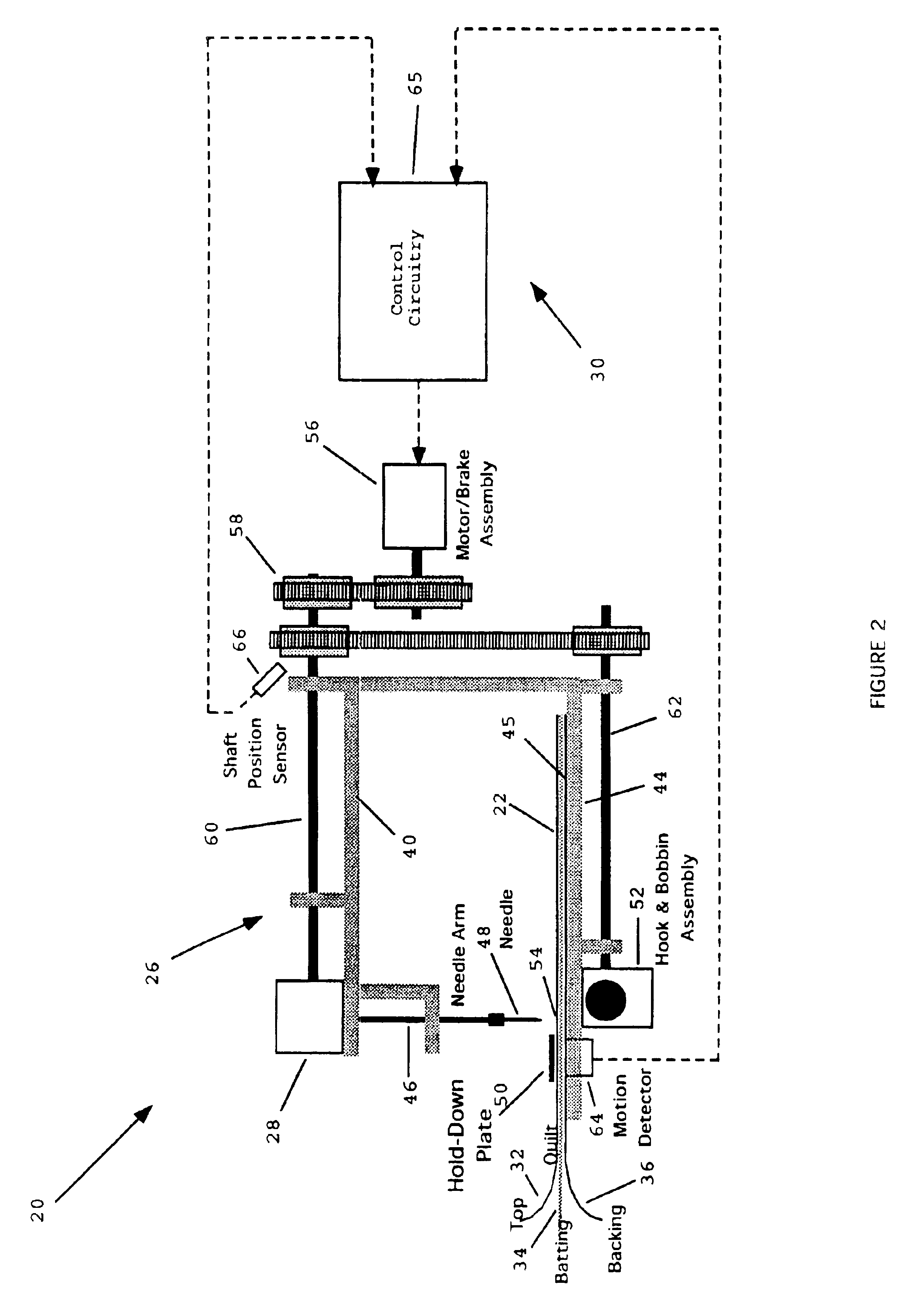
[0007]The present invention is directed to a system for fastening together two or more flexible planar layers and more particularly to a quilting method and apparatus for enabling a user to readily produce uniform stitches for fastening together a stack of fabric layers.
[0008]Apparatus in accordance with the invention permits a user to freely manually move a stack of planar layers across a planar bed, or plate, beneath an actuatable stitch head. The apparatus includes a detector for detecting the movement of the stack proximate to the stitch head for controlling actuation of the stitch head. Consequently, an apparatus in accordance with the invention functions to automatically synchronize the delivery of stitch strokes to the movement of the stack. This enables the user to move the stack within a wide range of speeds, to start or stop the stack movement at will, and to guide the stack in any direction across the planar bed.

Problems solved by technology

However, hand quilting is a labor-intensive process which can require many months of effort by a practiced person to create a single quilt.
Thus, free motion quilting with a conventional sewing machine requires significant user skill and yet frequently yields imperfect results, particularly when forming curved and intricate stitch patterns.

Method used


Image

  • Quilting method and apparatus
  • Quilting method and apparatus
  • Quilting method and apparatus

Examples


embodiment 68

[0043]FIG. 7 illustrates a second alternative system embodiment 68 which contains a mechanical machine portion 26′ and an electronic control subsystem 30′, similar to the corresponding portions 26 and 30 of the embodiment of FIG. 2. However, the embodiment of FIG. 7 differs from FIG. 2 primarily in that it uses a clutch / brake assembly 69 to control power transfer from motor 70 to the stitch head 28′, in lieu of the aforementioned motor / brake assembly 56 of FIG. 2. Additionally, the hook and bobbin assembly 52′ in FIG. 7 is driven continuously by motor 70 with the position of the bobbin hook (not shown) therein being sensed by a hook position sensor 71. The outputs of stack motion detector 64′, shaft position sensor 66′, and hook position sensor 71 are all applied as inputs to control circuitry 65′ whose output controls the clutch / brake assembly 69 to selectively actuate the stitch head 28′.

[0044]Attention is now directed to FIG. 9 which depicts a circuit diagram relevant to both the...

embodiment 175

[0055]With continuing reference to FIG. 12, note that the detector embodiment 175 is comprised of a housing 176 preferably mounted beneath the bed 144. The housing contains a light source 178 which transmits light through lens system 180 to produce a beam focused against the backing layer 36 of the quilt material stack 22. The reflected light from the backing layer is collected by lens system 182 and coupled to a photodetector 184. The photodetector 184 generates a detectable signal change for each thread crossing the focal point of the beam incident on the backing layer 36. The output of photodetector 184 drives an amplifier 186 to produce a pulse output 188 representing thread crossings, i.e., backing layer motion.

[0056]Attention is now directed to FIG. 13 which illustrates a circuit diagram of a control subsystem substantially identical to that shown in FIG. 9 except that it incorporates the optical motion detector 175 of FIG. 12 in lieu of the optical motion detector 64 of FIG. ...


PUM


Abstract

A quilting apparatus for enabling a user to freely move a stack of fabric layers across a planar bed relative to an actuatable stitch head. The apparatus includes a motion detector which detects the movement of the stack and controls the actuation of the stitch head. Consequently, the apparatus functions to synchronize the delivery of stitch strokes by the head with the manually controlled movement of the quilt material stack. This frees the user to move the stack over a wide range of speeds, to start or stop movement at will, and to guide the stack in any direction across the planar bed.

Description

RELATED APPLICATIONS[0001]This application claims the benefit of U.S. Provisional Application No. 60 / 447,159 filed 12 Feb. 2003.FIELD OF THE INVENTION[0002]This invention relates generally to a system for fastening together two or more flexible planar layers and more particularly to a method and apparatus for stitching together two or more fabric layers, as in quilting.BACKGROUND OF THE INVENTION[0003]Creating decorative quilts by hand has become a popular avocation. A typical quilt is comprised of at least two fabric layers which are stacked and stitched together. Generally the quilt is comprised of a “top” layer, a “bottom” or “backing” layer, and an intermediate “batting” layer. The top layer is typically decorative and is produced as a consequence of the creative and artistic effort of the quilt maker. The backing layer is usually simple and aesthetically compatible with the top. The batting layer generally provides bulk and insulation. The specific process of sewing the sandwic...

Claims


Application Information

Patent Timeline
Patent Type & Authority Patents(United States)
IPC IPC(8): D05B69/00D05B69/36D05B11/00D05B19/14D05B69/14D05B69/28
CPCD05B19/14D05B69/28D05B69/14D05B11/00D05B79/00
Inventor KOERNER, RALPH J.
Owner BERNINA SEWING MACHINE
Why Eureka
Try Eureka