Torsional assisted multi-position cam indexer having controls located in rotor

a multi-position, camshaft technology, applied in machine/engine, valve drive, coupling, etc., can solve the problems of significant leakage in terms of performance and oil consumption, increasing the likelihood of leakage, etc., to reduce leakage, shorten the fluid passage, and improve the response of the phaser

Inactive Publication Date: 2005-04-26
BORGWARNER INC
View PDF17 Cites 52 Cited by
  • Summary
  • Abstract
  • Description
  • Claims
  • Application Information

AI Technical Summary

Benefits of technology

[0017]The present invention is an infinitely variable camshaft timing device (phaser) with a control valve located in the rotor. Since the control valve is in the rotor, the camshaft need only provide a single passage for supplying engine oil or hydraulic fluid, and does not need multiple passageways for controlling the phaser, as was the prior art. The main advantage to putting the spool in the rotor is to reduce leakage and to improve response of the phaser. This design allows for shorter fluid passages when compared to a control system mounted at the cam bearing.
[0018]The rotor is connected to the camshaft, and the outer housing and gear move relative to the rotor and camshaft. Source oil is supplied through the center of the camshaft. In a preferred embodiment, the oil passes through an inlet check valve and is ported to the center of the spool valve. The inlet check valve eliminates oil from back flowing through the source during a torque reversal. The position of the spool valve determines if the phaser will advance or retard.

Problems solved by technology

This leakage is significant in terms of performance and oil consumption.
In all the systems described above, the controls for camshaft timing are located in the camshaft itself, or downstream of the camshaft, increasing the likelihood for leakage as the hydraulic fluid moves from the spool valve into the vanes of the rotor.

Method used


Image

  • Torsional assisted multi-position cam indexer having controls located in rotor
  • Torsional assisted multi-position cam indexer having controls located in rotor
  • Torsional assisted multi-position cam indexer having controls located in rotor

Examples


Embodiment Construction

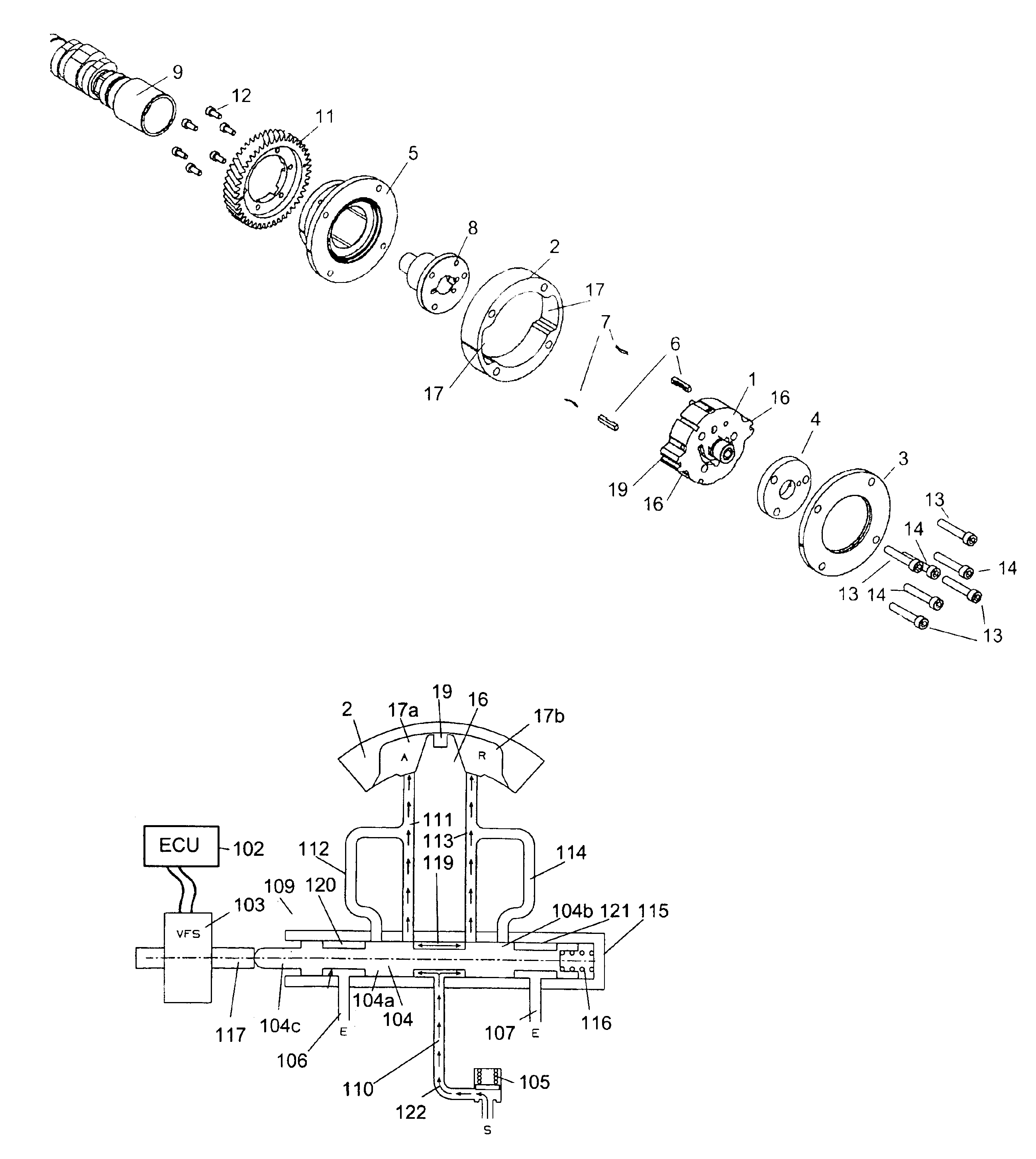
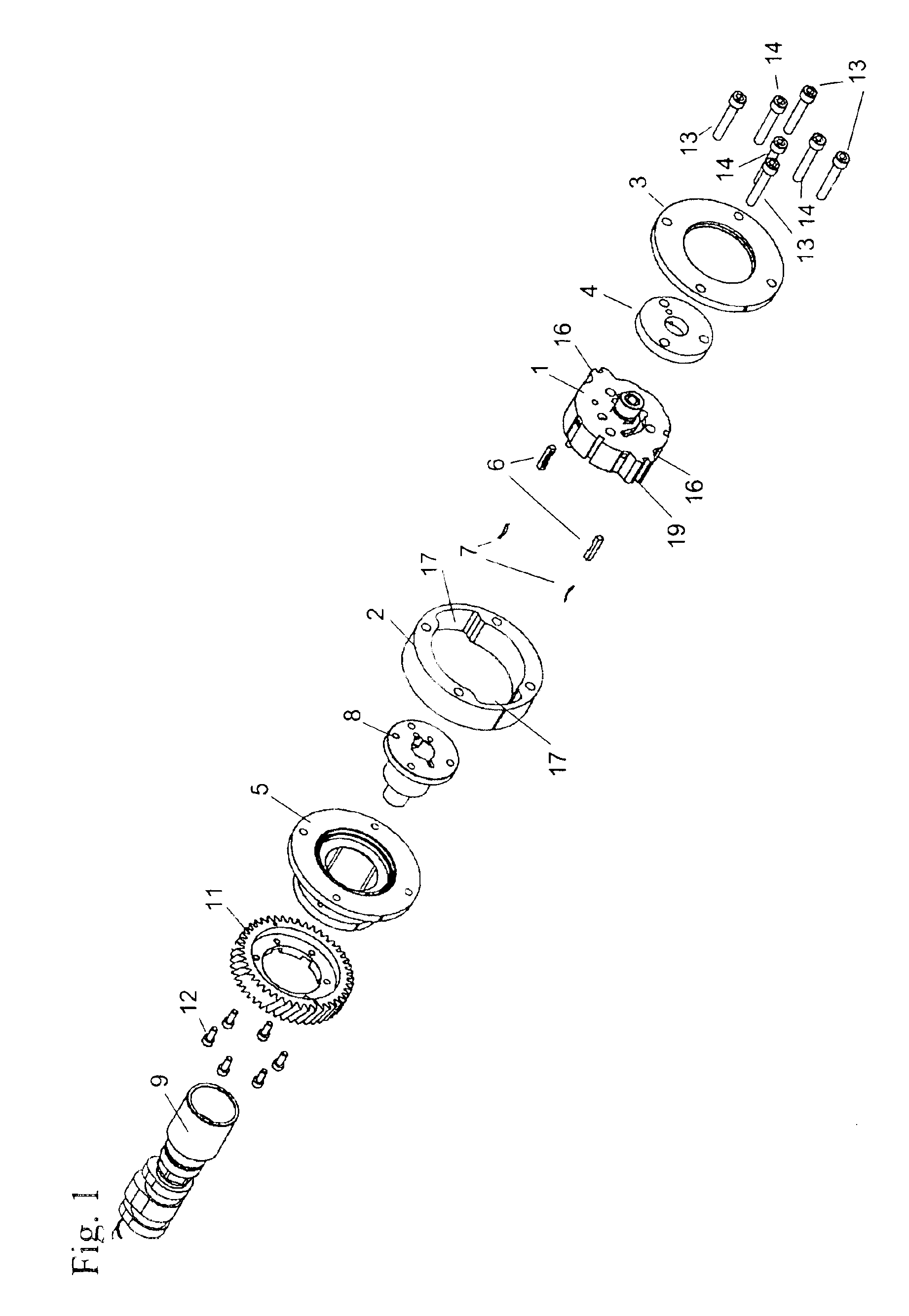
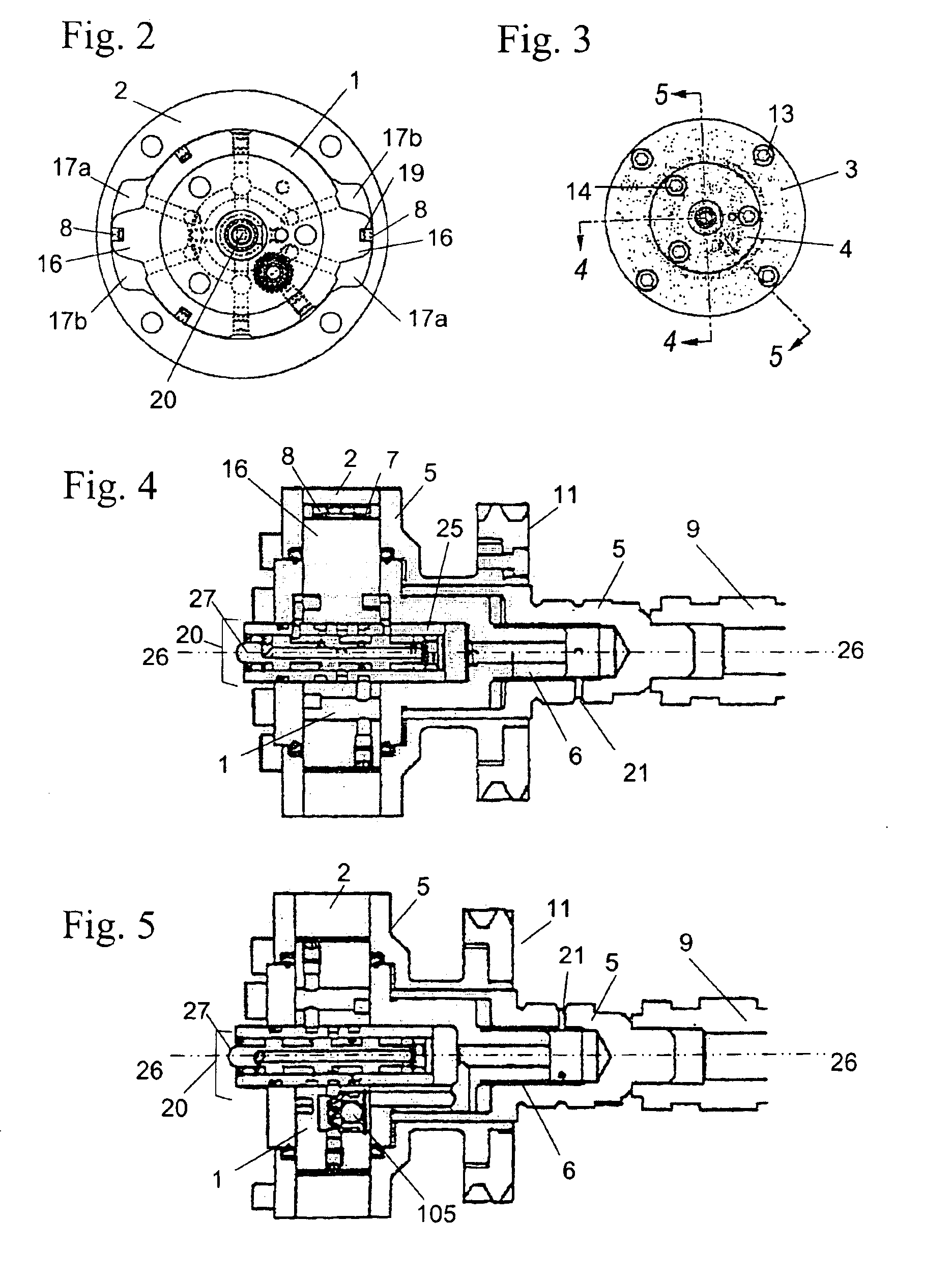
[0027]Referring to FIGS. 1 through 5, an internal combustion engine has a crankshaft, which is driven by the connecting rods of the pistons, and one or more camshafts, which actuate the intake and exhaust valves on the cylinders. The timing gear on the camshaft is connected to the crankshaft with a timing drive, such as a belt, chain or gears. Although only one camshaft (9) is shown in the figures, it will be understood that the camshaft (9) may be the only camshaft of a single camshaft engine, either of the overhead camshaft type or the in-block camshaft type, or one of two (the intake valve operating camshaft or the exhaust valve operating camshaft) of a dual camshaft engine, or one of four camshafts in a “V” type overhead cam engine, two for each bank of cylinders.

[0028]In a variable cam timing (VCT) system, the timing gear on the camshaft is replaced by a variable angle coupling known as a “phaser”, having a rotor connected to the camshaft and a housing connected to (or forming)...


PUM


Abstract

An infinitely variable cam indexer utilizes engine oil pressure to actuate a cam and preferably uses an inlet check valve in the oil source to minimize back flow during a torque reversal. The control system is in the center of the rotor and uses an electromechanical actuator, preferably a variable force solenoid, acting directly on the spool to control oil flow. This design reduces leakage and improves the response of the phaser. There are shorter oil passages as compared to a control system mounted at the cam bearing.

Description

REFERENCE TO RELATED APPLICATIONS[0001]This is a continuation application of application Ser. No. 10 / 198,318, filed Jul. 18, 2002 now abandoned, entitled “HYBRID MULTI-POSITION CAM INDEXER HAVING CONTROLS LOCATED IN ROTOR”, which claims an invention which was disclosed in Provisional Application No. 60 / 312,285, filed Aug. 14, 2001, entitled “HYBRID MULTI-POSITION CAM INDEXER HAVING CONTROLS LOCATED IN ROTOR”. The benefit under 35 USC §119(e) of the U.S. provisional application is hereby claimed, and the aforementioned applications are hereby incorporated herein by reference in their entireties.BACKGROUND OF THE INVENTION[0002]1. Field of the Invention[0003]The invention pertains to the field of variable camshaft timing (VCT) systems. More particularly, the invention pertains to an infinitely variable camshaft indexer with controls in the center of the rotor.[0004]2. Description of Related Art[0005]There are many vane type VCTs on the market today that use a conventional 4-way valve ...

Claims


Application Information

Patent Timeline
Patent Type & Authority Patents(United States)
IPC IPC(8): F01L1/344F01L1/34
CPCF01L1/34F01L1/344F01L1/3442F01L1/34409F01L2001/34426
Inventor GARDNER, MARTYDUFFIELD, MICHAEL
Owner BORGWARNER INC
Why Eureka
Try Eureka