
Redrawn capillary imaging reservoir

a reservoir and capillary technology, applied in the field of high density array printing, can solve the problems of limited density of arrays and limited printing processes, and achieve the effect of uniform reduction of cross-sectional dimensions and areas

Inactive Publication Date: 2005-04-26
CORNING INC
View PDF114 Cites 34 Cited by
  • Summary
  • Abstract
  • Description
  • Claims
  • Application Information

AI Technical Summary

Benefits of technology

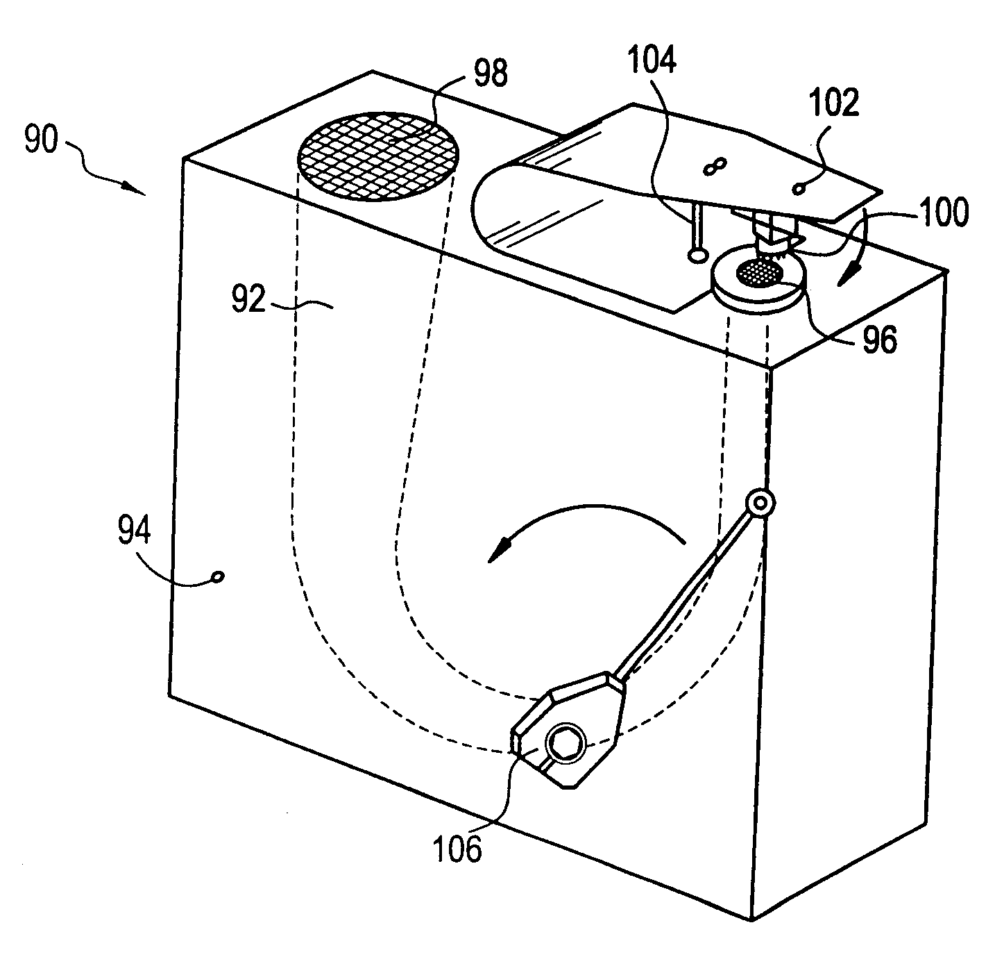
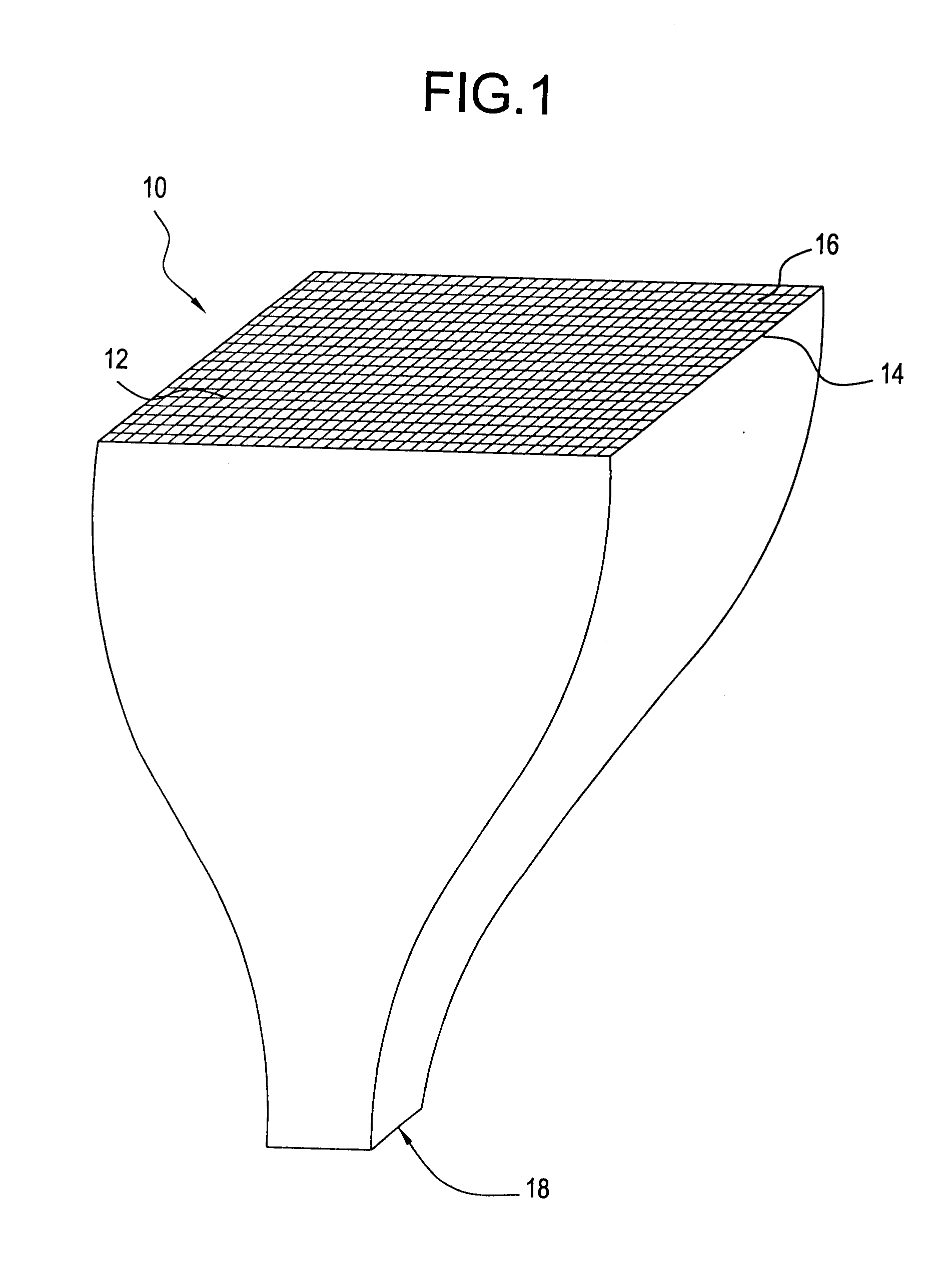
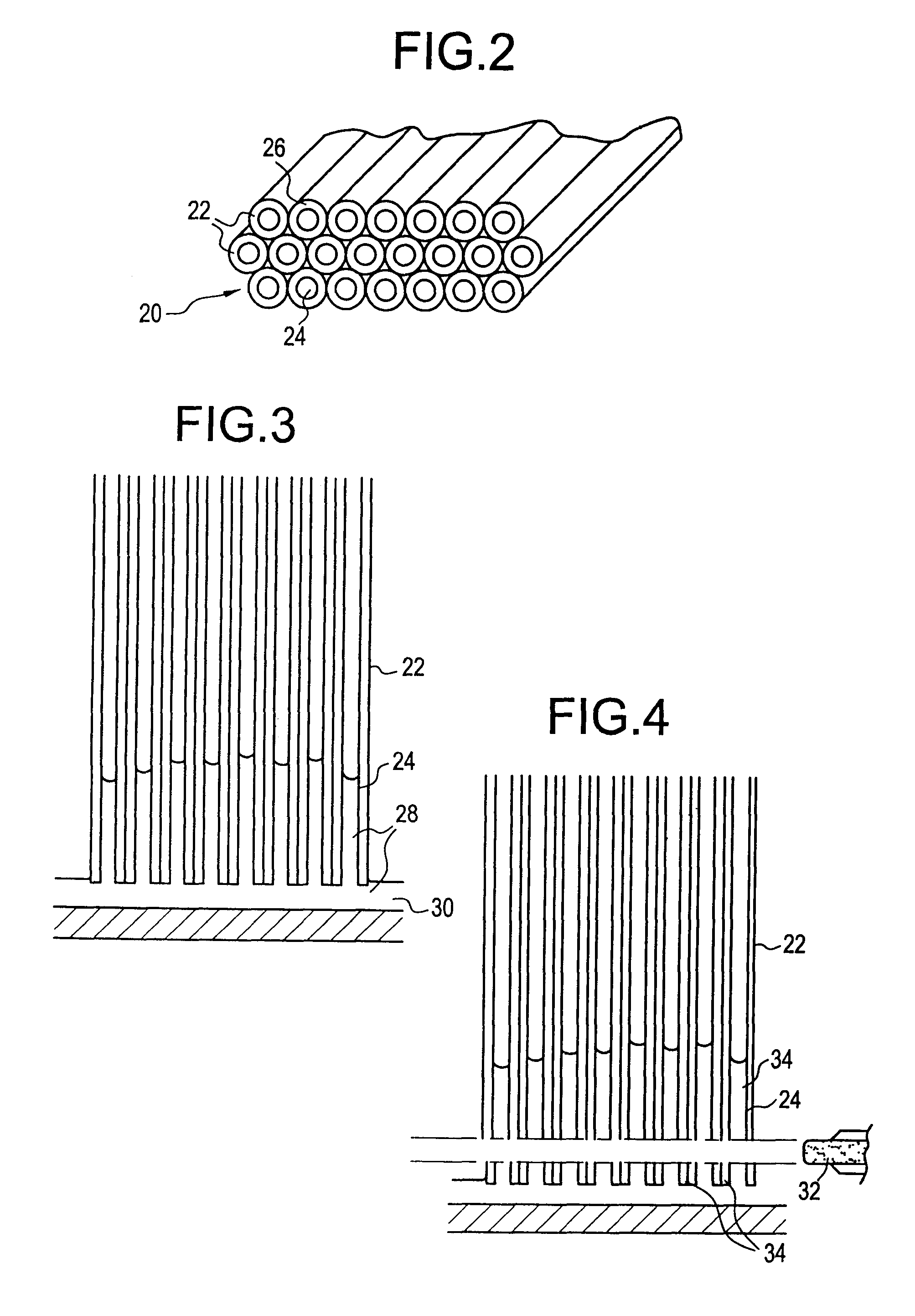
The present invention provides a device for depositing a high density biological or chemical array onto a substrate. The device has a matrix made up of multiple open ended channels, where the channels on the loading end have a larger pitch than the channels on the liquid delivery end. The upper portion of each channel acts as a reservoir, while the opposite end is designed to retain liquid by capillary pressure. The device has uniform cross-sectional dimensions and areas throughout its height. Additionally, the invention provides a variation of the device that can transfer samples between multiwell plates of different well density.

Problems solved by technology

All other base pairs are mismatches that destabilize hybrids.
The density of the arrays is limited by this process.
These printing processes are limited by the time and expense required in transferring 103 or greater different sequence mixtures onto defined positions on a substrate.

Method used


Image

  • Redrawn capillary imaging reservoir
  • Redrawn capillary imaging reservoir
  • Redrawn capillary imaging reservoir

Examples


example

Extrusion and Sintering

[0038]Table 1 shows the composition of PYREX 7761 glass. The inorganic powder is made from PYREX 7761 cullet: crushed, magnetically separated, ball milled (alumina), and ultrasonically screened (−325 mesh).

[0039]

TABLE 1CompoundWeight Percent (%)SiO278.92K2O2.76B2O318.27

[0040]Table 2 shows the batch composition of the extrudable mixture.

[0041]

TABLE 2IngredientsWeight (grams)PYREX 7761 powder7938Oleic Acid80Dow F-40M METHOCEL558Water (DI)1985

[0042]The inorganic powder, the METHOCEL, and the Oleic Acid are blended together in a LITTLEFORD mixer, and then mulled together with the water addition in a LANCASTER mixer. The mix is then further mixed by evacuation and spaghetti extrusion (3 times). Finally, the batch is extruded through a die to be formed into a multi-celled preform which is cut from the extrudate, ready for sintering.

[0043]Table 3 shows the furnace schedule used to sinter the preforms. The preforms are vertically suspended during sintering to minimize...


PUM

PropertyMeasurementUnit
radiusaaaaaaaaaa
radiusaaaaaaaaaa
center-to-center distanceaaaaaaaaaa

Abstract

Methods and apparatus for depositing a high density biological or chemical array onto a solid support. Specifically, the apparatus is made up of a plurality of open ended channels collectively forming a matrix. The matrix has been redrawn and cut such that the pitch of the channels on the loading end is larger than the pitch of the channels on the liquid delivery end. The upper portion of each channel serves as a reservoir, while the opposing end, which has been formed by the redrawing process, is diametrically sized such that liquid in the reservoir is retained by capillary pressure at the delivery end. At any point along the height of the capillary reservoir device, all cross-sectional dimensions and areas are uniformly reduced. In other words, the on-center orientation of any two channels, also referred to as the pitch between 2 channels, measured as a function of the diameter of any cross section, is constant throughout the structure. The liquid within the channels is either printed directly from the tool onto a substrate or transferred to a substrate by a typographical pin plate. In another embodiment, the device may be used in transferring sample between multiwell plates of different well density.

Description

[0001]This application is a continuation-in-part of U.S. application Ser. No. 09 / 299,766 filed on Apr. 26, 1999, now U.S. Pat. No. 6,596,237, which claims the benefit both of Provisional Application No. 60 / 091,707 filed on Jul. 3, 1998 and of European Application No. 98401021.5 filed on Apr. 27, 1998, and this application also is a continuation-in-part of U.S. application Ser. No. 09 / 300,121 filed on Apr. 29, 1999, now U.S. Pat. No. 6,350,618, which claims the benefit of both Provisional Application No. 60 / 091,707 filed on Jul. 3, 1998 and of European Application number 98401021.5 filed on Apr. 27, 1998.FIELD OF INVENTION[0002]The invention relates to a device and method for the printing of high density arrays for use in biological and chemical assays as well as a device that can be used in sample transfer between multiwell plates of differing well density.BACKGROUND OF INVENTION[0003]Hybridization is a hydrogen- bonding interaction between two nucleic acid strands that obey the Wat...

Claims


Application Information

Patent Timeline
Patent Type & Authority Patents(United States)
IPC IPC(8): B01L3/00B01L3/02B01J19/00C03B19/06C03B37/02C03B23/00C03B23/047C03B23/06C03B37/028G01N33/543G01N35/10G01N35/00C40B40/06C40B60/14C40B70/00
CPCG01N35/1067B01J19/0046B01L3/0244B01L3/50857B01L3/563C03B19/06C03B23/047C03B23/06C03B37/028G01N33/54306Y10T436/2575G01N2035/1037G01N2035/1069B01J2219/00274B01J2219/0031B01J2219/00315B01J2219/00317B01J2219/00369B01J2219/00378B01J2219/005B01J2219/00511B01J2219/00547B01J2219/00549B01J2219/00585B01J2219/00596B01J2219/00605B01J2219/0061B01J2219/00612B01J2219/00621B01J2219/00626B01J2219/00637B01J2219/00644B01J2219/00648B01J2219/00659B01J2219/00673B01J2219/00722B01L2200/021B01L2300/0838C40B40/06C40B60/14C40B70/00G01N35/1065Y10T436/25G01N2035/00237G01N1/16
Inventor BORRELLI, NICHOLAS F.CARRE, ALAIN R. E.DANNOUX, THIERRY L. A.EID, BERNARDROOT, DAVIDWUSIRIKA, RAJA RAO
Owner CORNING INC
Learn More