Localized stress relief by induction heating

a stress relief and induction heating technology, applied in the field of induction heating, can solve the problems of inefficient conduits, induced current flow with associated resistive losses, heat generation, etc., and achieve the effect of reducing the area of metal plates and high magnetic permeability

Inactive Publication Date: 2005-04-26
THE BOEING CO
View PDF7 Cites 27 Cited by
  • Summary
  • Abstract
  • Description
  • Claims
  • Application Information

AI Technical Summary

Benefits of technology

[0006]According to a preferred embodiment of the present invention, an apparatus is provided to heat and stress relieve a metal plate area. A susceptor assembly is constructed using one or more sheets of material having preselected Curie temperatures. The Curie temperature is defined as the sheet temperature at which magnetic permeability equals unity. The individual susceptor sheets are assembled into a semi-flexible assembly by welding the individual sheets at their adjoining edges, forming pairs of sheets. The susceptor assembly is positioned over a metal plate in the area adjacent to a weld joint in the associated weld zone area. The susceptor assembly is sized to approximate the area where stress relief of the weld zone is required. A housing is then mounted over the susceptor assembly covering the susceptor assembly and a portion of the metal plate area. An induction coil is positioned within the housing adjacent to the susceptor assembly. An oscillating electric current is passed through the induction coil which induces an electromagnetic flux. This flux then couples with the susceptor assembly. The susceptor assembly has high magnetic permeability, which makes the susceptor assembly the lowest energy path for the electromagnetic flux to reside. Coupling the electromagnetic flux in the susceptor assembly causes an induced current flow with associated resistive losses (heating). Heat generated by this process conductively and convectively passes from the susceptor assembly to the weld zone of the metal plate area. The susceptor assembly, based on its multi-sheet design, allows a thermal gradient of temperatures to be applied to the metal plate area at the weld zone.
[0009]A ferritic material in the form of a ferritic plate is also cut and formed to fit on a perimeter of the susceptor assembly. The ferritic material is selected from a non-electrically conductive material also having high magnetic permeability. The ferritic material captures and induces the lines of magnetic flux from a perimeter of the susceptor sheets and directs the lines of magnetic flux toward the weld joint located approximately at the center of the susceptor assembly. The ferritic plates act as both a concentrator and as an insulator to prevent the lines of magnetic flux from heating the surrounding area outside of the susceptor assembly therefore containing heat output from the susceptor assembly in the immediate area of the weld zone.

Problems solved by technology

Coupling the electromagnetic flux in the susceptor assembly causes an induced current flow with associated resistive losses (heating).
The magnetic flux coupled through the susceptor material causes a rapid heat-up of the susceptor material up to the Curie point of each sheet at which point the susceptor material becomes an inefficient conduit for the magnetic flux since the material above its Curie point becomes non-magnetic.

Method used


Image

  • Localized stress relief by induction heating
  • Localized stress relief by induction heating
  • Localized stress relief by induction heating

Examples


Embodiment Construction

[0019]The following description of the preferred embodiment(s) is merely exemplary in nature and is in no way intended to limit the invention, its application, or uses.

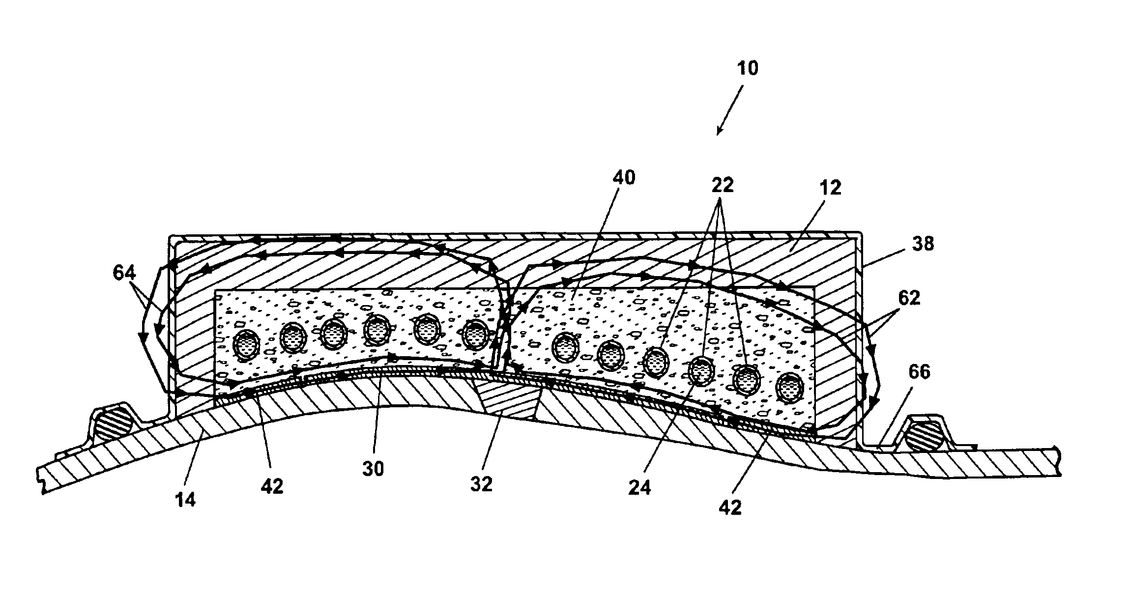
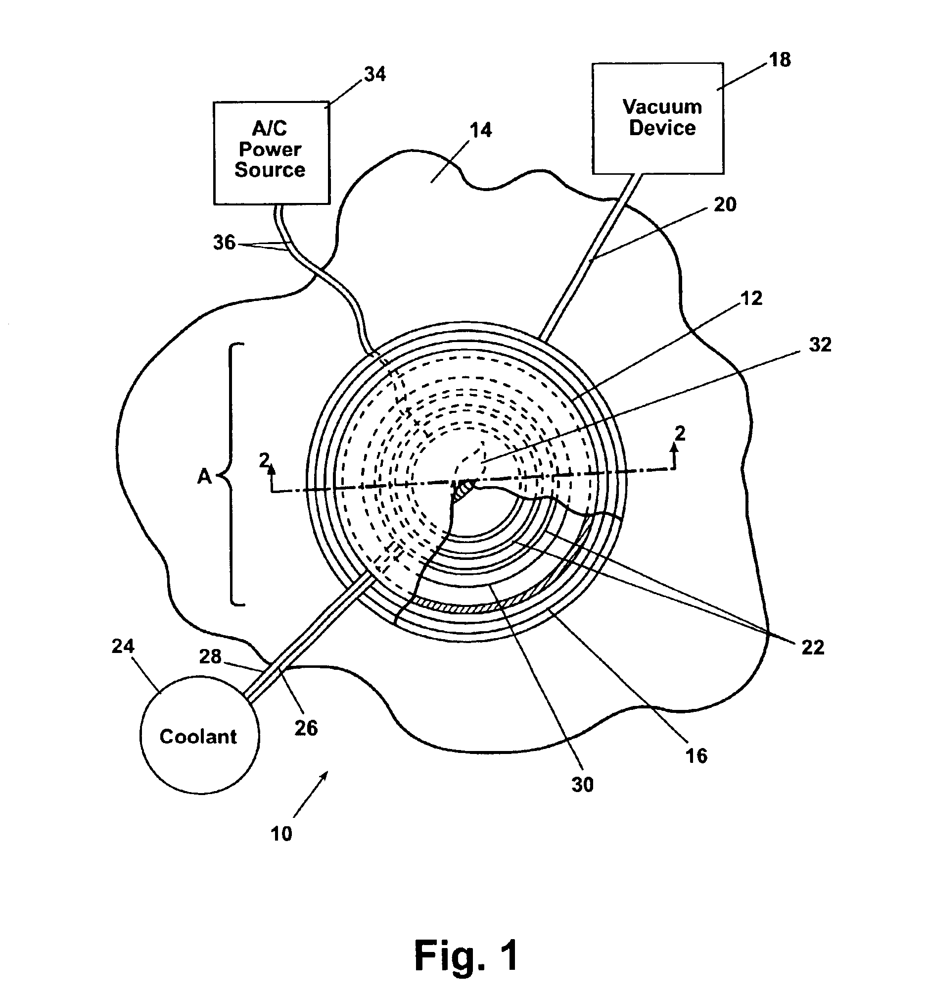
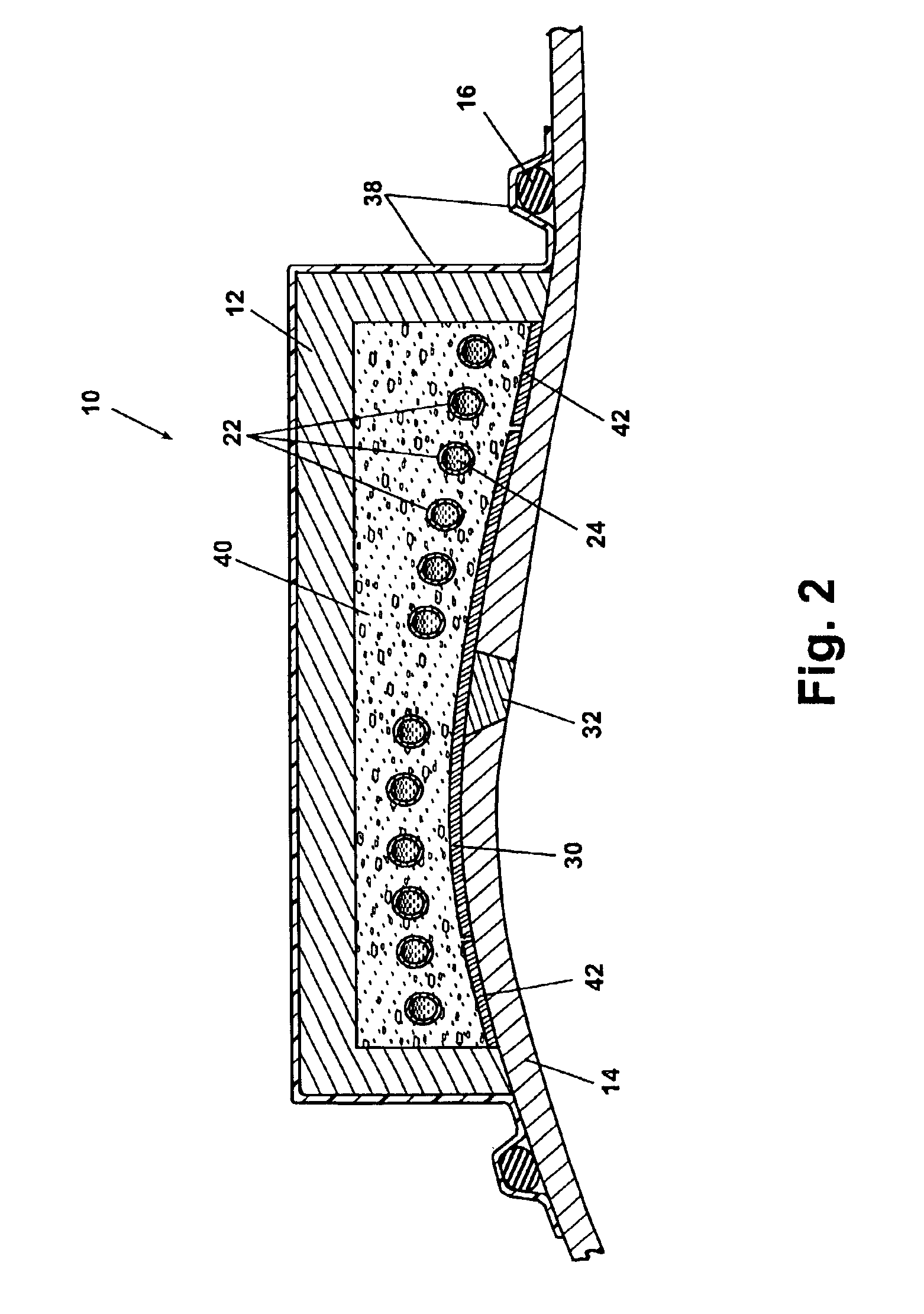
[0020]Referring to FIG. 1, an induction heating system 10 according to a preferred embodiment of the present invention is shown. The induction heating system 10 includes a tool body 12 which is temporarily affixed to a weld surface 14. The tool body 12 is held in place on the weld surface 14 at a vacuum seal 16. A vacuum device 18 draws a partial vacuum within the vacuum seal 16 through a vacuum tube 20. A geometrically arranged induction coil 22 is disposed within the tool body 12. A supply of coolant 24 is provided to cool the induction coil 22. The coolant 24 flows within the generally tubular shaped induction coil 22 as will be further described in reference to FIG. 3. The coolant 24 is provided via a coolant supply pipe 26 and returns after cooling the induction coil 22 via a coolant return pipe 28.

[0021]A suscep...


PUM

PropertyMeasurementUnit
Curie temperatureaaaaaaaaaa
temperaturesaaaaaaaaaa
areaaaaaaaaaaa

Abstract

A system and method inductively heats and stress relieves a weld joint area having a stress induced zone. A susceptor assembly is positioned over the stress induced zone. The susceptor assembly includes susceptor sheets manufactured to operate at different, preselected Curie temperatures. A housing is mounted over the susceptor assembly including an induction coil positioned adjacent to the susceptor assembly. An alternating electric current is applied to the induction coil. The alternating electric current causes the induction coil to generate a plurality of magnetic flux lines. The invention provides the advantage that the magnetic flux lines passing through the susceptor assembly heat the susceptor assembly providing localized and controlled temperature heat to the weld joint area to stress relieve the stress induced zone.

Description

FIELD OF THE INVENTION[0001]The present invention relates in general to induction heating and more specifically to systems and methods to use induction heating for post weld stress relief of welded parts.BACKGROUND OF THE INVENTION[0002]Following a welding procedure, many metals exhibit increased residual stresses in the area adjacent to the weld zone. A weld zone is defined herein as a weld joint and the adjacent area surrounding the weld joint in a metal, wherein the material properties of the metal are affected by residual stresses following the weld procedure. This residual stress can be modeled using an exemplary finite element model to identify the value of the stress and therefore identify the amount of post-weld heat required to relieve the stress in the area of the weld zone. Computational models therefore exist to identify a temperature gradient required adjacent to the weld zone to relieve the residual stress in the material.[0003]If the residual stress remaining in the m...

Claims


Application Information

Patent Timeline
Patent Type & Authority Patents(United States)
IPC IPC(8): H05B6/02
CPCC21D1/30C21D1/42H05B6/105C21D9/50H05B2206/023Y02P10/25
Inventor MATSEN, MARC R.SMITH, TERRY L.
Owner THE BOEING CO
Why Eureka
Try Eureka