
High efficiency transparent organic light emitting devices

a light emitting device, high efficiency technology, applied in the direction of electric discharge tube/lamp manufacture, discharge tube luminescnet screen, discharge tube, etc., can solve the problem of significant reflection from the compound cathode, undesired angular dependence of the emitted light, and degrade the device efficiency. problem, to achieve the effect of high efficiency

Inactive Publication Date: 2005-04-26
THE TRUSTEES FOR PRINCETON UNIV
View PDF51 Cites 40 Cited by
  • Summary
  • Abstract
  • Description
  • Claims
  • Application Information

AI Technical Summary

Benefits of technology

[0020]Another advantage of the invention is that the highly efficient transparent cathode may be used to advantage in other types of optoelectronic devices.
is that the highly efficient transparent cathode may be used to advantage in other types of optoelectronic devices.

Problems solved by technology

Although a device with about 70% transmission may be obtained, there is still significant reflection from the compound cathode.
Such microcavity effects may also lead to an undesired angular dependence of the emitted light.
Therefore, the non-metallic cathode improves transparency but degrades device efficiency.
This improves quantum efficiency, but the device was not transparent.

Method used


Image

  • High efficiency transparent organic light emitting devices
  • High efficiency transparent organic light emitting devices
  • High efficiency transparent organic light emitting devices

Examples


Embodiment Construction

[0029]The present invention will now be described in detail for specific preferred embodiments of the invention. These embodiments are intended only as illustrative examples and the invention is not to be limited thereto.

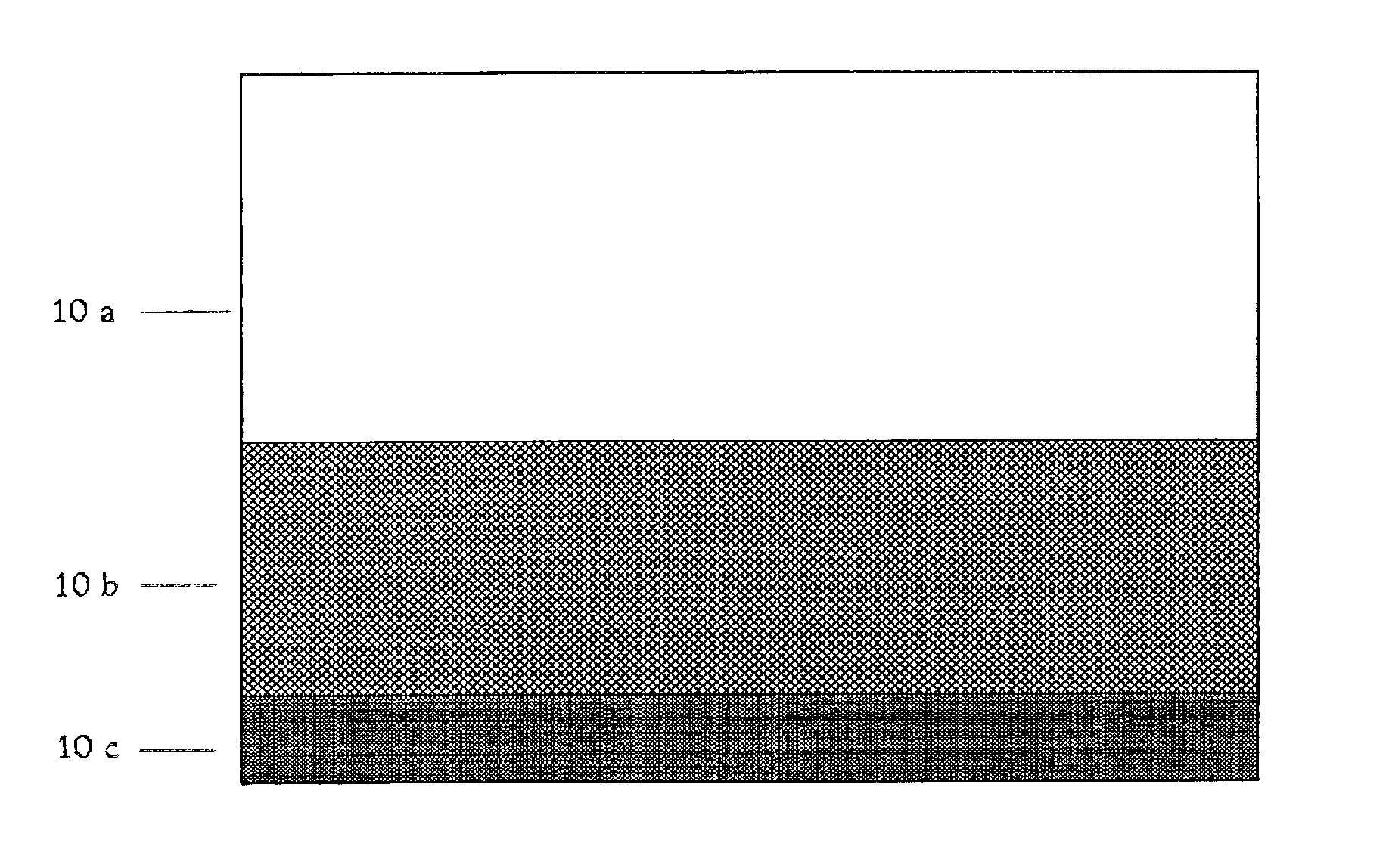
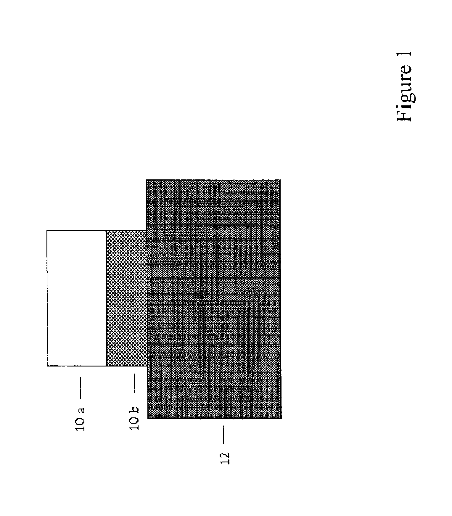
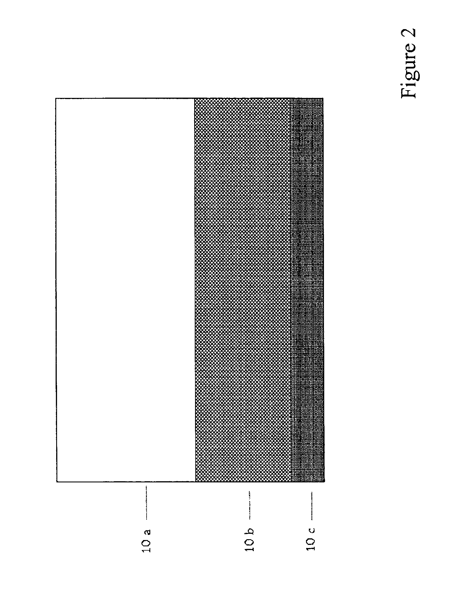
[0030]The present invention is directed to a novel cathode comprised of a metal-doped organic electron injection layer that is in direct contact with a transparent, non-metallic, electron injecting cathode layer, such as ITO, wherein the metal-doped organic electron injection layer also functions as an exciton blocking layer and / or as a hole blocking layer. The metal-doped organic electron injection layer is created by diffusing an ultra-thin layer of a highly electropositive metal throughout the layer. Such cathodes may be employed in a wide range of organic optoelectronic devices, such as OLEDs, solar cells, photodetectors, lasers and phototransistors. OLEDs incorporating such cathodes are shown herein to have what are believed to be the highest reported combinati...


PUM

PropertyMeasurementUnit
external quantum efficiencyaaaaaaaaaa
transparencyaaaaaaaaaa

Abstract

A highly transparent non-metallic cathode is disclosed that comprises a metal-doped organic electron injection layer that is in direct contact with a transparent non-metallic electron injecting cathode layer, such as indium tin oxide (ITO), wherein the metal-doped organic electron injection layer also functions as an exciton blocking or hole blocking layer. The metal-doped organic electron injection layer is created by diffusing an ultra-thin layer of about 5-10 Å of a highly electropositive metal such as Li throughout the layer. A representative embodiment of the highly transparent non-metallic cathode comprises a layer of ITO, a layer of 2,9-dimethyl-4,7-diphenyl-1,10-phenanthroline (BCP), which acts as an electron injection, exciton blocking, and hole blocking layer, and an ultra-thin layer of lithium, which degenerately dopes the layer of BCP, improving the electron injecting properties of the BCP layer. This cathode is demonstrated for use in an OLED having a transparency of about 90% or higher combined with a device external quantum efficiency of about 1% or higher.

Description

CROSS-REFERENCE TO RELATED APPLICATION[0001]This application is a continuation of U.S. patent application Ser. No. 09 / 522,155 filed Mar. 9, 2000, now U.S. Pat. No. 6,639,357, which claims the benefit of U.S. Provisional Application Ser. Nos. 60 / 188,613, filed Mar. 8, 2000 and 60 / 1 85,232, filed Feb. 28, 2000.RESEARCH AGREEMENTS[0002]The claimed invention was made by, on behalf of, and / or in connection with one or more of the following parties to a joint university-corporation research agreement: Princeton University, The University of Southern California, and the Universal Display Corporation. The agreement was in effect on and before the date the claimed invention was made, and the claimed invention was made as a result of activities undertaken within the scope of the agreement.FIELD OF THE INVENTION[0003]The present invention relates to highly efficient and highly transparent organic light emitting devices (OLEDs) using cathodes comprised of a transparent, non-metallic, electron i...

Claims


Application Information

Patent Timeline
Patent Type & Authority Patents(United States)
IPC IPC(8): H01L51/52H01L51/50H01L51/05H01L51/30A61B17/00A61B17/22A61B18/00A61F2/958A61F7/00A61F7/12A61M25/00H05B33/10H05B33/28H10K99/00
CPCA61F7/123H01L51/5052H01L51/5092H01L51/5096H01L51/5221H01L51/5234A61B18/00H01L2251/558A61B2017/22051A61B2018/00095A61F2007/126A61M25/00A61M25/1011A61M2025/1072A61M2025/1086H01L51/0078H01L51/0081H01L2251/5323A61B2017/00084H10K85/311H10K85/324H10K50/165H10K50/171H10K50/18H10K50/828H10K2102/3031H10K2102/351H05B33/26
Inventor PARTHASARATHY, GAUTAMADACHI, CHIHAYABURROWS, PAUL E.FORREST, STEPHEN R.
Owner THE TRUSTEES FOR PRINCETON UNIV
Learn More