Non-contact communication medium

Inactive Publication Date: 2005-04-26
SEIKO EPSON CORP
View PDF19 Cites 26 Cited by
  • Summary
  • Abstract
  • Description
  • Claims
  • Application Information

AI Technical Summary

Benefits of technology

[0061]Also, in view of production, merely forming the first pad part, the second pad part, the third pad part, the fourth pad part, the conducting part, and the loop antenna on the one side of the circuit board simplifies the production process.
[0062]Thus, for recycling, the communication circuit can be removed from the circuit board by merely removing the entire arm part from the circuit board. Therefore, recycling can be preformed more easily than the conventional examples. Also, since there is no need to prov

Problems solved by technology

However, in the first conventional example, since the insulating resin layer is provided on the first conducting part between the innermost circumference and the outermost circumference of the loop antenna and the second conducting part for connecting the innermost circumference to the IC chip is provided on the insulating resin layer, there is a problem in that the complicated production process makes the production difficult.
Also, in the second and third conventional examples, the structure in which an arm part comprising a conducting part for connecting the other end of the loop antenna to the IC chip is provided and in which collapsing the arm part causes the other end of the loop antenna to be connected to the IC chip causes a problem that stress applied to the folding part of the arm part of the loop antenna is likely to cause cracking.
First, since an IC chip on which data is stored is mounted on a circuit board, data may be leaked out in the process of recycling.
Second, although a loop antenna portion is easy to recycle due to its uncomplicated structure, an IC chi

Method used


Image

  • Non-contact communication medium
  • Non-contact communication medium
  • Non-contact communication medium

Examples


first embodiment

[0136]The embodiments of the present invention will now be described with reference to the drawings. FIGS. 1 to 5 show a non-contact communication medium according to the present invention.

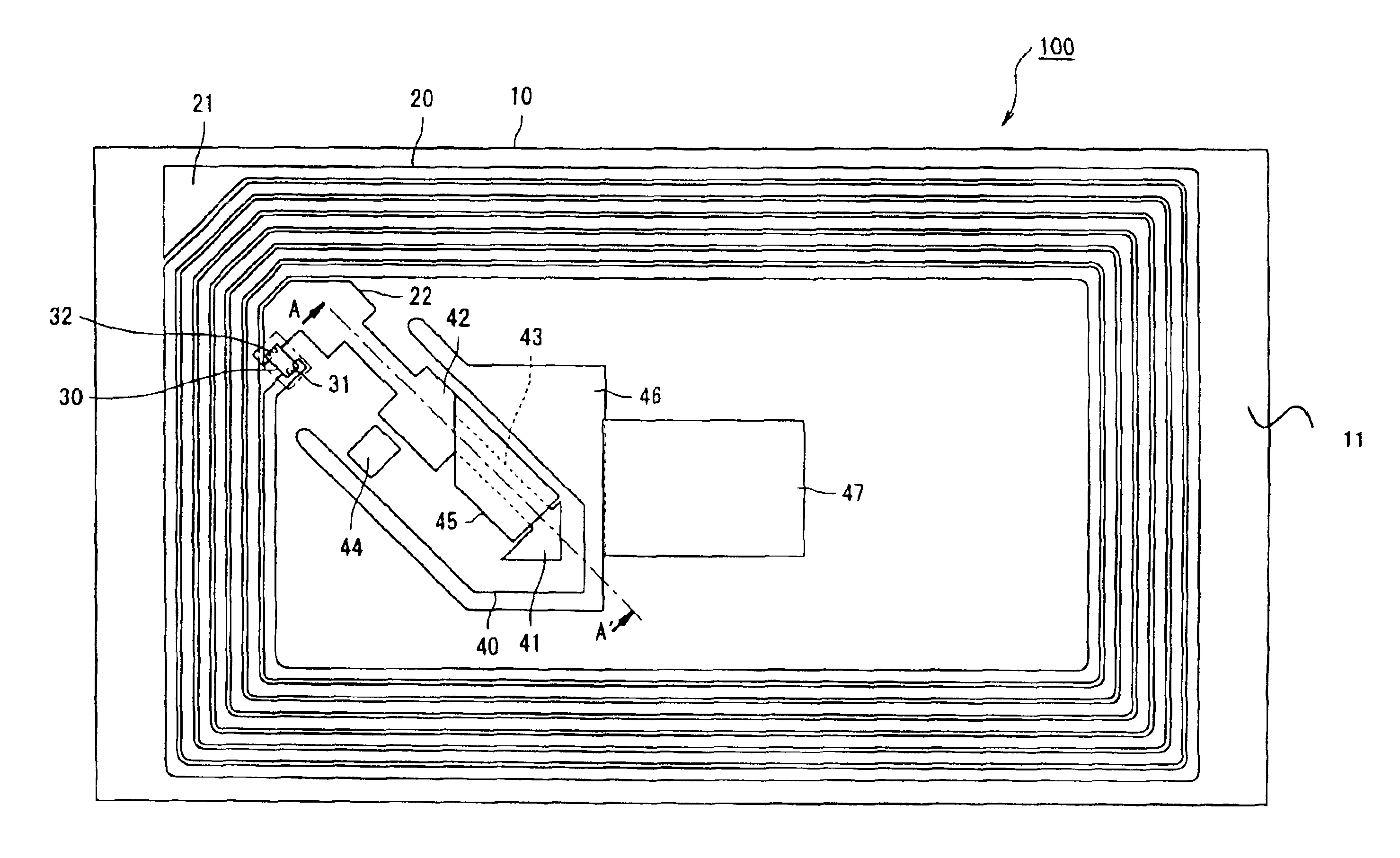
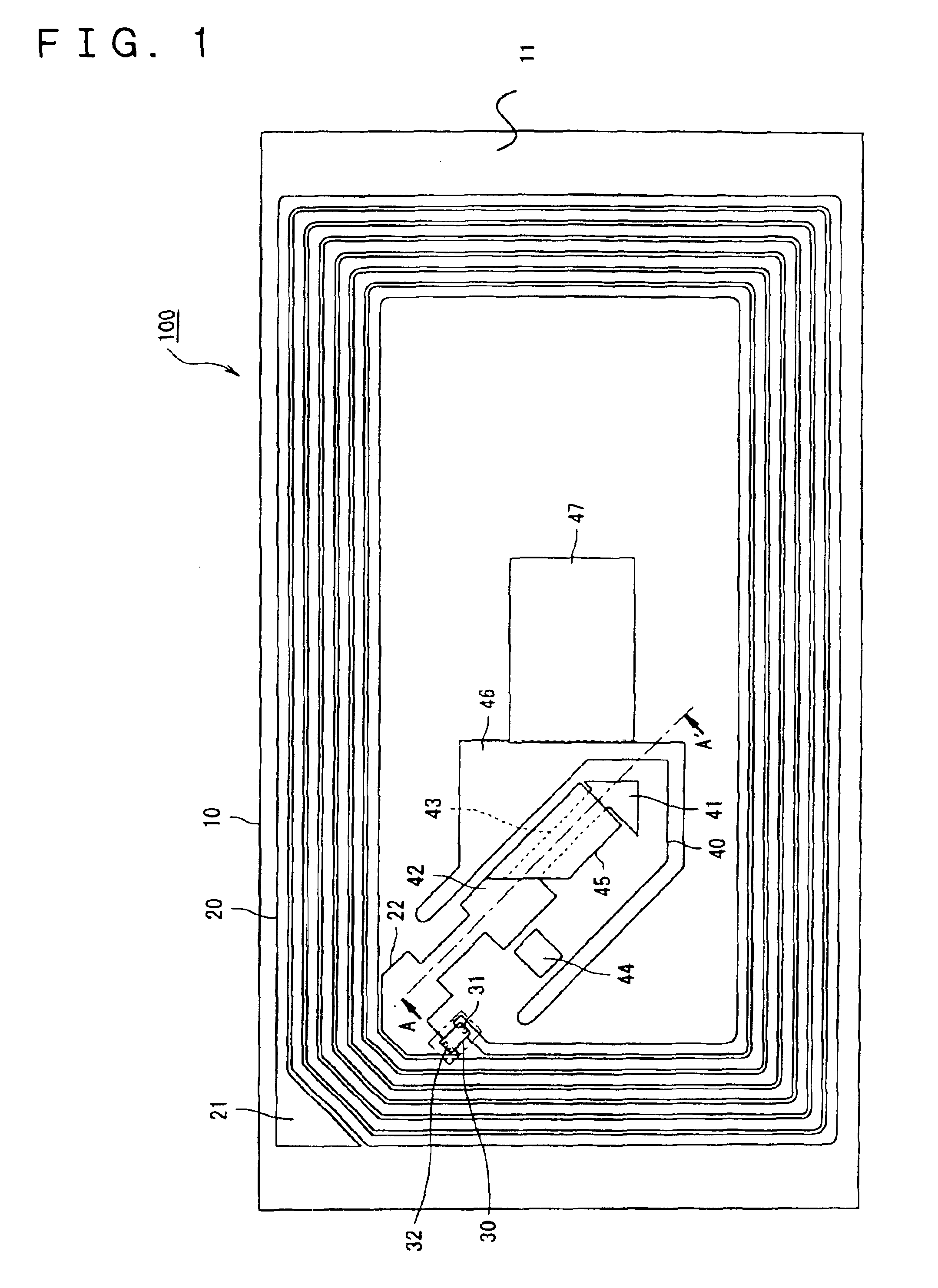
[0137]In the first embodiment, the non-contact communication medium according to the present invention is applied to an RFID non-contact IC tag 100, as shown in FIG. 1.

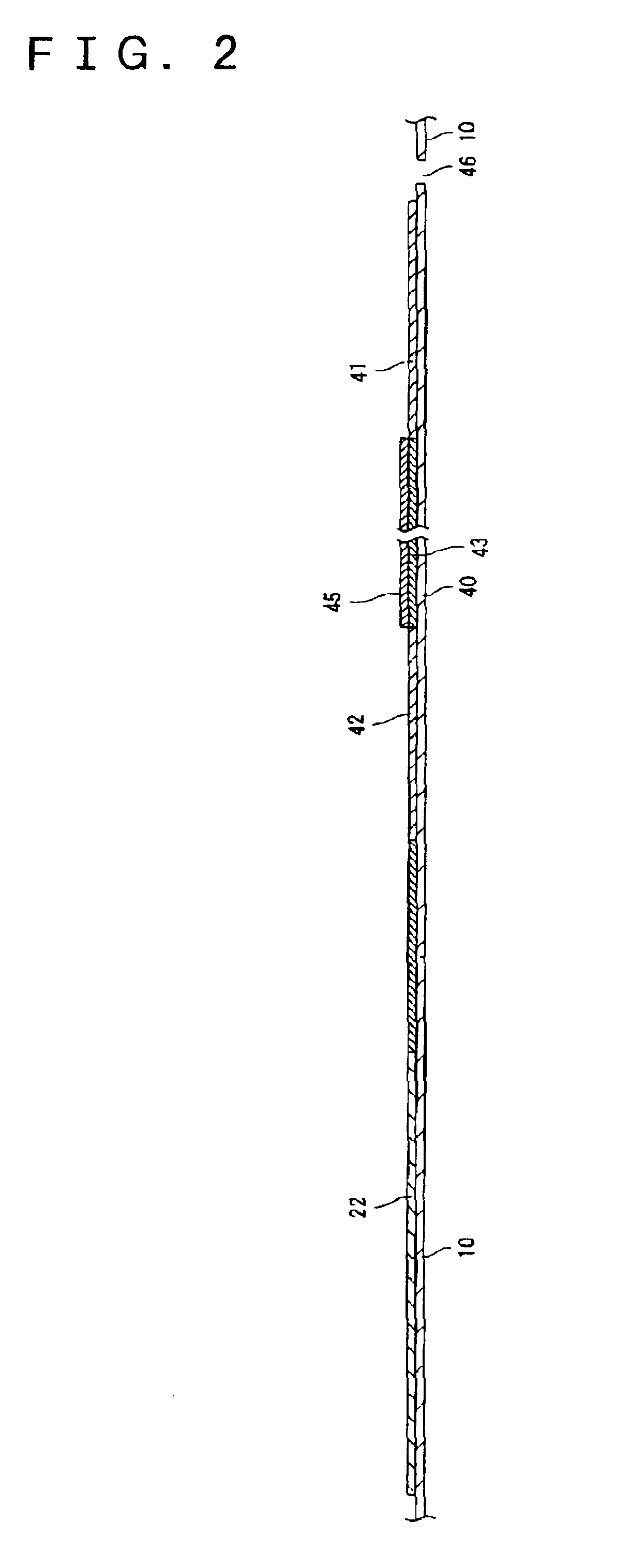
[0138]The structure of the RFID non-contact IC tag 100 according to the present invention will now be described with reference to FIGS. 1 to 4. FIG. 1 is a plan view of the RFID non-contact IC tag 100 when an arm part 40 is not collapsed. FIG. 2 is a cross-sectional view taken along the line A-A′ in FIG. 1. FIG. 3 is a plan view of the RFID non-contact IC tag 100 when the arm part 40 is collapsed. FIG. 4 is a cross-sectional view taken along the line A-A′ in FIG. 3.

[0139]As shown in FIGS. 1 and 3, the RFID non-contact IC tag 100 comprises a circuit board 10, a loop antenna 20 formed on one side 11 of the circuit board 10, an IC chip...

second embodiment

[0234]For recycling, the joints are removed and the arm part 40 joined to the circuit board 10 is pulled by pinching a leading edge of the arm part 40, so that the arm part 40 is removed from the circuit board 10. Here, this operation is made easier by providing the notch 60, as in the After removing the arm part 40 from the circuit board 10, the circuit board 10 is recycled and the arm part 40 is disposed of.

[0235]Accordingly, in this embodiment, a capacitor is formed by the conductive pattern 48 provided on the arm part 40 and the loop antenna 20 provided on the circuit board 10. Thus, a predetermined resonance frequency can be achieved together with the capacitor part of the IC chip 30.

[0236]Thus, the area of an antenna surface is wider than a case where capacitors are arranged on the front and back of a circuit board. Therefore, the reduction in the communication quality can be suppressed.

[0237]Furthermore, part of the conductive pattern 48 is removable.

[0238]Thus, the capacita...

third embodiment

[0256]In the third embodiment, the IC chip 30 corresponds to a communication circuit according to Invention 20, 25, or 31. The antenna connection terminals 31 and 32 and the pad part 22 correspond to antenna connection parts according to Invention 20 or 24. The pad part 41 corresponds to a first pad part according to Invention 20, and the pad part 42 corresponds to a second pad part according to Invention 20 or 24. Also, the conducting wire 43 corresponds to a conducting part according to Invention 20 or 23. The conductive pattern 48 corresponds to a conductive pattern according to Invention 20, 21, or 22, and the RFID non-contact IC tag 102 corresponds to a non-contact communication medium according to Inventions 20 to 31.

[0257]Although, in the first embodiment, the heat-radiating material 44 is provided at a position of the arm part 40 where the arm part 40 overlaps the IC chip 30 when the arm part 40 is collapsed, a heat-absorbing material may be provided at a position of the arm...


PUM


Abstract

A loop antenna is formed on one side of a circuit board and an IC chip is mounted on the same side of the circuit board. An inner end of the loop antenna is connected to an antenna connection terminal of the IC chip. An arm part provided with a first pad part, a second pad part, and a conducting wire for allowing conduction between the fist pad part and the second pad part is collapsibly provided in such a manner that, when the arm part is collapsed, an outer end of the loop antenna contacts the first pad part and an antenna connection terminal of the IC chip contacts the second pad part.

Description

BACKGROUND OF THE INVENTION[0001]1. Technical Field[0002]The present invention relates to a non-contact communication medium in which a loop antenna made of a conductor is formed on a circuit board and in which a communication circuit is mounted on the circuit board, more specifically, to a non-contact communication medium suitable for facilitating the production and for preventing cracking in the loop antenna, furthermore to a non-contact communication medium suitable for recycling, for facilitating the production, and for preventing cracking in a bridge coupling part of the loop antenna, and even furthermore to a non-contact communication medium suitable for improving the antenna efficiency and for easily adjusting the resonance frequency of the communication circuit.[0003]2. Related Art[0004]Conventionally, for example, an electronic tag disclosed in Japanese Unexamined Patent Application Publication No. 9-198481 (hereinafter, referred to as a first conventional example), a remot...

Claims


Application Information

Patent Timeline
IPC IPC(8): G06K19/077H05K3/46H05K1/11B42D15/10G06K19/07G09F3/00H01Q1/22H01Q1/38H01Q7/00H01Q7/02H04B5/02
CPCG06K19/07728G06K19/07749G06K19/0775H01Q1/22H01Q7/00H05K3/4685H01Q1/38H05K2201/09081H05K1/118H05K2201/055
Inventor TAKEI, YOSHIKI
Owner SEIKO EPSON CORP
Why Eureka
Try Eureka