
Electronic apparatus

a technology of electronic equipment and equipment, applied in the direction of power cables, semiconductor/solid-state device details, cables, etc., can solve the problems of affecting the performance of the pump, and not taking into account the conventional arts, so as to improve the processing performance, improve the heat generation effect, and stabilize the cooling

Inactive Publication Date: 2005-04-26
MAXELL HLDG LTD
View PDF20 Cites 13 Cited by
  • Summary
  • Abstract
  • Description
  • Claims
  • Application Information

AI Technical Summary

Benefits of technology

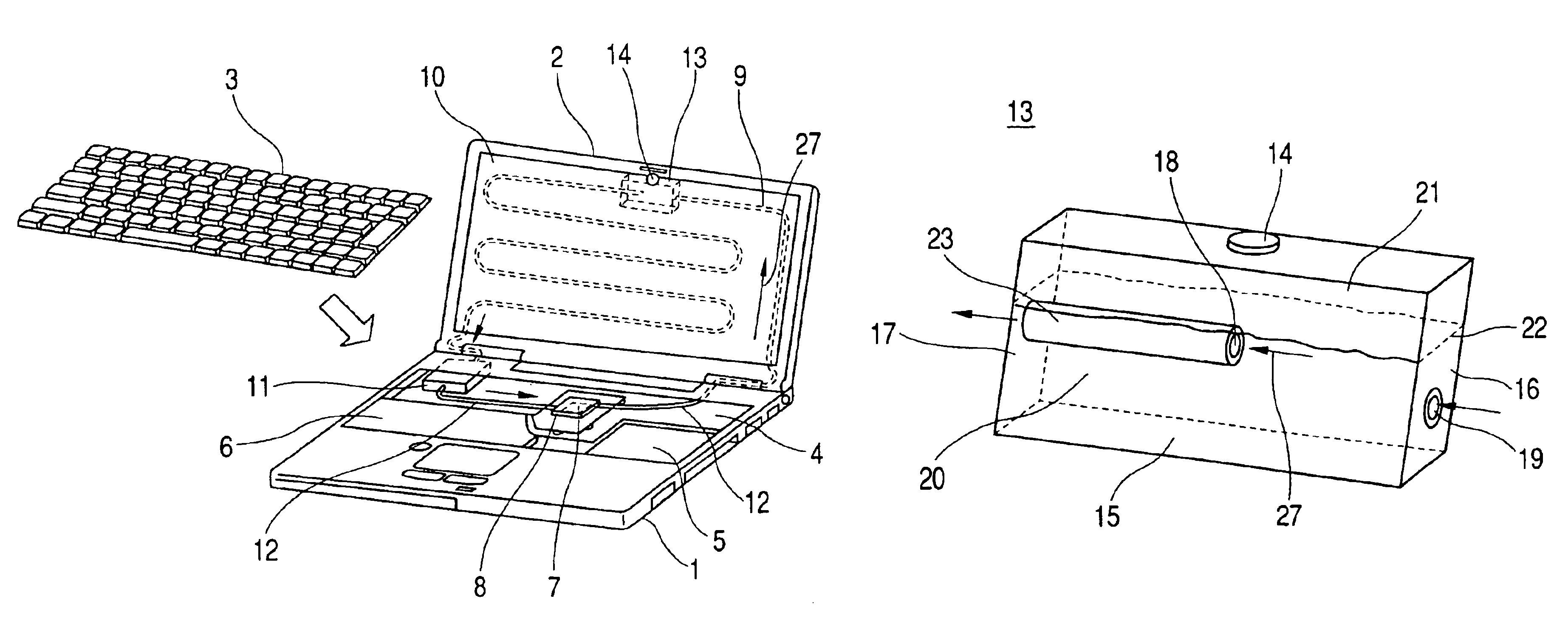
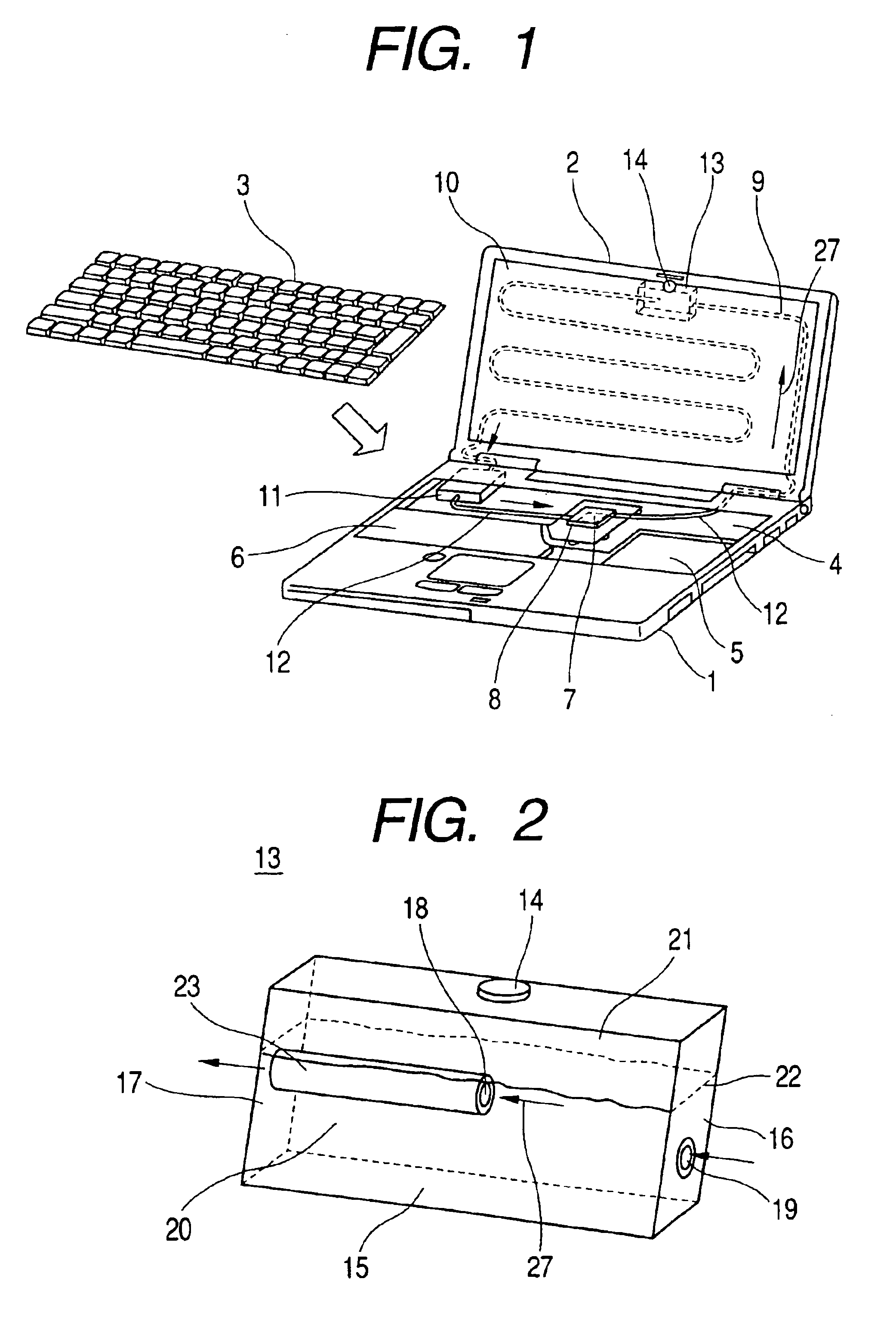
[0009]An object is, therefore, according to the present invention, by taking such the drawbacks of the above-mentioned conventional arts into the consideration, to provide an electronic equipment or apparatus, in particular, a portable (movable) and small-sized electronic equipment or apparatus, being able to deal with an increase of heat-generation from the heat-generating element accompanying with an improvement in processing performance thereof in recent years, wherein a stable cooling can be obtained by circulating and / or supplying a liquid coolant with stability therein.

Problems solved by technology

However, none of those conventional arts takes into the consideration, of mixing of the air when the tank is moved (i.e., being turned upside down).
Namely, with the conventional arts mentioned above, there may be a fear that the pump may suck a gas, such as the air, when operating.
In this instance, in particular, in a case where it is applied into a water-cooling system for the electronic apparatus relating to the present invention, there may occur a problem that performance comes down remarkably, in cooling, therefore the cooling cannot be achieved fully for the heat-generating element.

Method used


Image

  • Electronic apparatus
  • Electronic apparatus
  • Electronic apparatus

Examples


Embodiment Construction

[0037]An electronic equipment or apparatus, such as a so-called personal computer, includes a notebook-type personal computer, which is portable, and a desktop-type personal computer, which is mainly used on a desk. With each of those personal computers, being demanded to be higher and larger in processing speed and capacity thereof every year, temperature of the heat generation of a CPU, i.e., the semiconductor element, comes up to be higher, as a result of those requirements. And it is expected that this tendency will continue further, in future.

[0038]On the contrary to this, in general, the personal computers are mainly of an air-cooling type by means of a fan or the like, or a heat or thermo-conductive type, at the present situation. Those cooling method have a limit in the capacity of heat-radiation, and there is a possibility that they cannot follow the heat-radiation of the CUP, which is on such the tendency of high heat-generation, as was mentioned above. However, it may be ...


PUM


Abstract

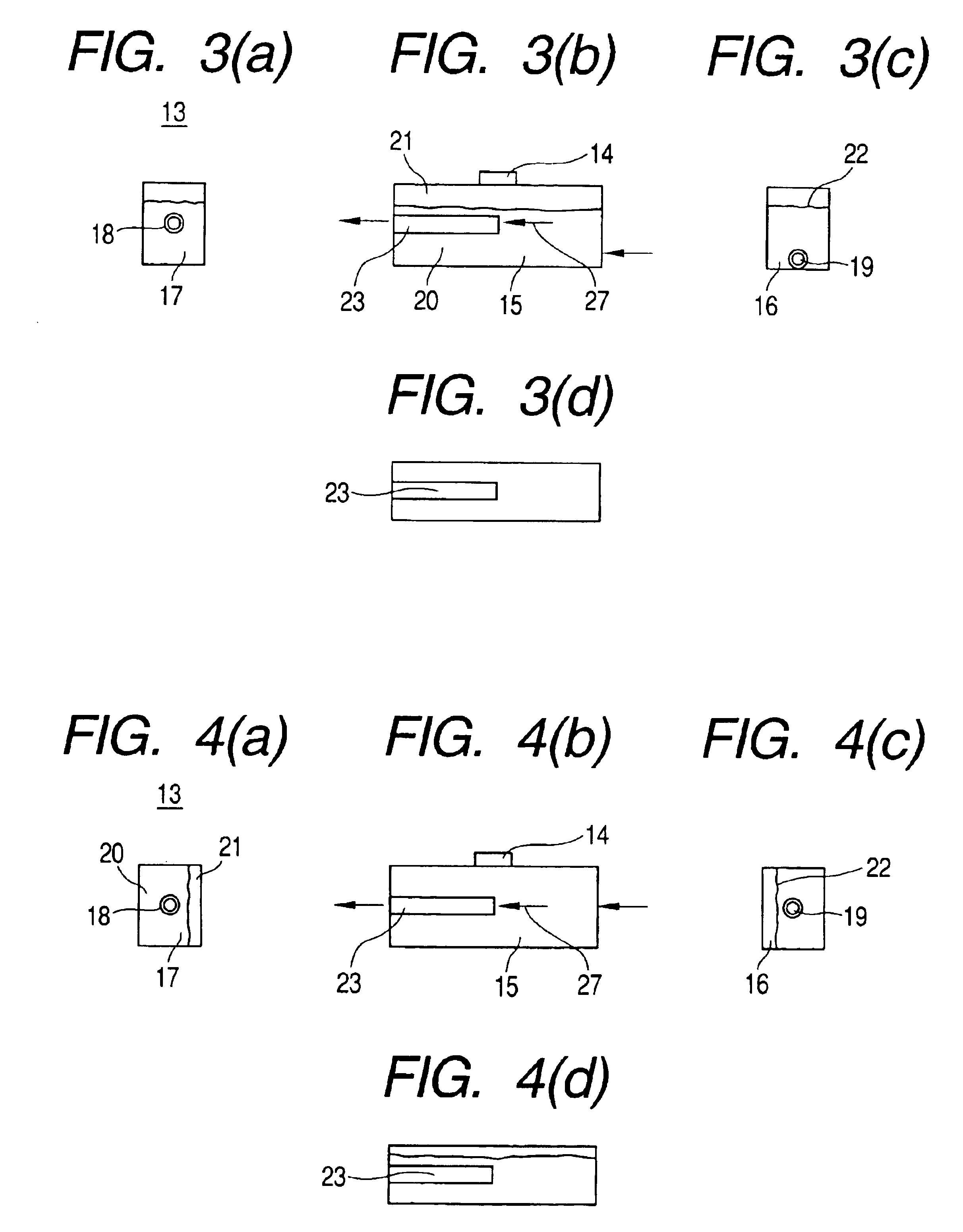
An electronic apparatus includes a case mounting a semiconductor element within an inside thereof, a heat-receiving member thermally connected with the semiconductor element, a heat-radiation member disposed on an inner side surface of the casing, and a liquid driver for driving a liquid coolant between the heat-radiation member and the heat-receiving member. The apparatus further includes a tank accumulating the liquid coolant therein with at least a predetermined volume of the coolant to delimit a coolant surface within the tank, wherein the tank, the heat-radiation member and the heat-receiving member are connected with tubes, and a suction end portion of a suction pipe connected into the tank is located at a position which is always below the coolant surface irrespective of change of position of the tank.

Description

CROSS REFERENCE TO RELATED APPLICATION[0001]This is a continuation of U.S. application Ser. No. 10 / 239,155, filed May 6, 2003 now U.S. Pat. No. 6,257,169, the subject matter of which is incorporated by reference herein and is a 371 of PCT / JP02 / 07008, filed Jul. 10, 2002.TECHNICAL FIELD[0002]The present invention relates to an electronic equipment or apparatus, in which a semiconductor element is cooled through a liquid circulating therein.BACKGROUND ART[0003]Conventional electronic equipment or apparatus, including a water-cooling device therein and also being portable, is already known, for example, in Japanese Patent Laying-Open No. Hei 7-142886 (1995), and Japanese Patent Laying-Open No. 2001-24372 (2001).[0004]Also, an electronic apparatus is already known, relating to the conventional art, in which a tank is disposed within a piping system of a water-cooling module for cooling a heat-generating part thereof, for example, in Japanese Patent Laying-Open No. Hei 6-125199 (1994), a...

Claims


Application Information

Patent Timeline
Patent Type & Authority Patents(United States)
IPC IPC(8): G06F1/20H05K7/20H01L23/473H01L23/34
CPCG06F1/203G06F2200/201H01L23/473H01L2924/0002H01L2924/00
Inventor KONDO, YOSHIHIROMATSUSHITA, SHINJIOHASHI, SHIGEONAGANAWA, TAKASHIMINAMITANI, RINTARONAKAGAWA, TSUYOSHIYOSHITOMI, YUUJINAKANISHI, MASATOKATOU, HAJIME
Owner MAXELL HLDG LTD
Learn More