
Method to produce stress-free optical waveguides to reduce stress-induced birefringence in planar lightwave circuit (PLC) devices

a planar lightwave circuit and waveguide technology, applied in the direction of optical waveguide light guide, instruments, optics, etc., can solve the problems of birefringence or polarization sensitivity is undesirable for most optical devices, and the waveguide b>20/b> actually affecting the optical performance. to achieve the effect of reducing the stress gradien

Inactive Publication Date: 2005-04-26
HEADWAY TECH INC
View PDF8 Cites 0 Cited by
  • Summary
  • Abstract
  • Description
  • Claims
  • Application Information

AI Technical Summary

Benefits of technology

The present invention provides a method for making waveguides with reduced stress gradients. This is achieved by creating a structure with an underclad layer and a core layer. The core layer is then patterned to form the waveguide, and a portion of the underclad layer is overetched to create a projection underneath the waveguide. This results in a waveguide with reduced stress gradients and an overetched underclad layer with reduced stress gradients.

Problems solved by technology

The stress difference in these two directions causes the refractive index values to be different resulting in stress-induced birefringence.
The birefringence or the polarization sensitivity is undesirable for most optical devices.
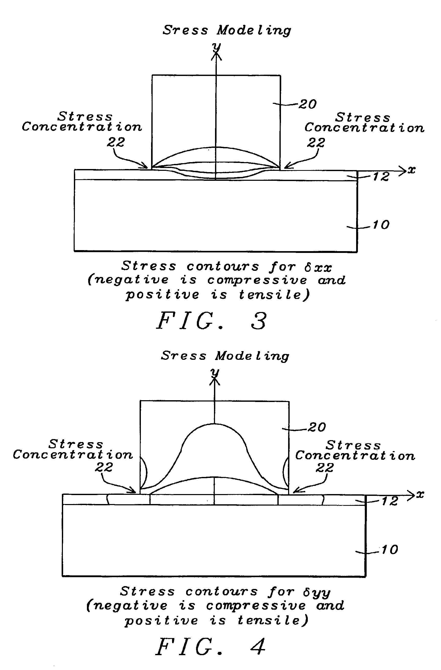
While the wafer bow is undesirable due to wafer handling concerns during subsequent processing, the stress in the waveguide 20 actually affects the optical performance due the stress-optics effects.
This polarization sensitivity is undesirable for many types of optical devices.
It may be greater although that would impact upon the process time and would reduce the benefit.
Additionally, the increased process time needed to etch greater that about one-half the waveguide width may have a negative impact.

Method used


Image

  • Method to produce stress-free optical waveguides to reduce stress-induced birefringence in planar lightwave circuit (PLC) devices
  • Method to produce stress-free optical waveguides to reduce stress-induced birefringence in planar lightwave circuit (PLC) devices
  • Method to produce stress-free optical waveguides to reduce stress-induced birefringence in planar lightwave circuit (PLC) devices

Examples


Embodiment Construction

Method / Problem Known to the Inventors—Not to be Considered Prior Art for the Purposes of the Present Invention

[0018]Planar Lightwave Circuit (PLC) is the technology of constructing optical devices on substrates similar to making semiconductor devices or magnetic heads. Optical waveguides of silica are formed on either silica substrates or silicon substrates. Such optical waveguides, are generally rectangular in shape and are formed by employing an etching process such as, for example, a reactive-ion etch (RIE) process.

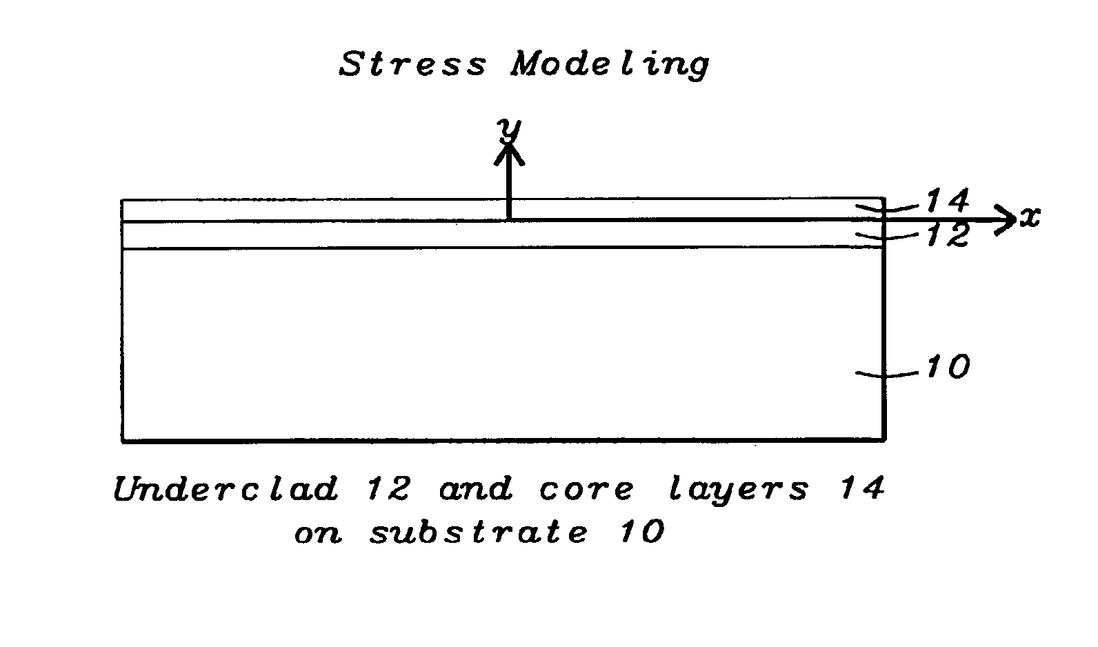
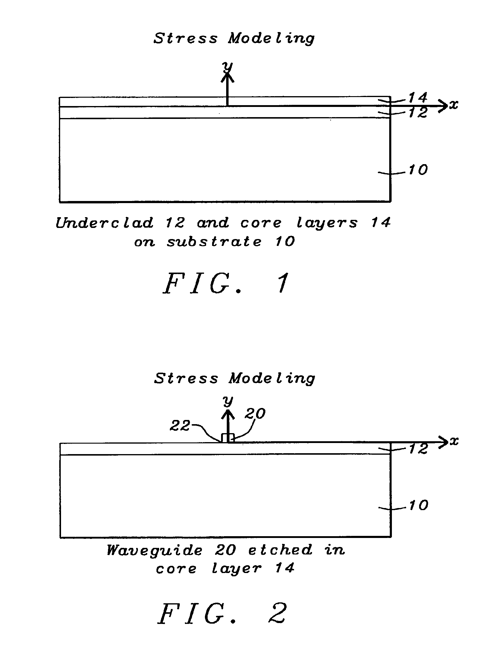
[0019]The PLC process begins with the deposition of a layer of underclad material on the substrate followed by a layer of core material. A pattern of waveguides of the optical device to be formed is etched into the core layer, preferably by using a mask. The overclad material is then deposited to fill the space around the waveguides and also to provide a layer on top of the waveguides. The refractive index of the core layer is generally higher than that of the undercla...


PUM


Abstract

A method of forming a waveguide comprising the following steps. A structure is provided. An underclad layer is formed over the structure and a core layer is formed over the underclad layer. Patterning: the core layer to form the waveguide; and partially into the underclad layer, forming an overetched underclad layer having a projection underneath the waveguide. The waveguide having stress gradients and the overetched underclad layer having stress gradients.

Description

FIELD OF THE INVENTION[0001]The present invention relates generally to optical planar lightwave circuit (PLC) device fabrication and more specifically to methods of forming waveguides.BACKGROUND OF THE INVENTION[0002]A major cause of stress-induced birefringence is the stresses in the optical waveguides resulting from the mismatch in the thermal expansion coefficients between the substrate and the waveguide material(s). This causes the refractive index and the light propagation properties to be dependent upon the direction of polarization and hence polarization dependent loss.[0003]Conventional methods to reduce the stress in waveguides involve using substrate material with thermal expansion coefficients closely matching that of the core.[0004]U.S. Publication No. 2002 / 0074308 A1 to Beguin describes a method of manufacturing a planar waveguide with a core and overclad layers.[0005]U.S. Publication No. 2002 / 0097962 A1 to Yoshimura et al. describes single and multilayer waveguides and...

Claims


Application Information

Patent Timeline
Patent Type & Authority Patents(United States)
IPC IPC(8): G02B6/13G02B6/132G02B6/12G02B6/10
CPCG02B6/132G02B6/105G02B2006/12173G02B2006/121
Inventor CHHABRA, DEVENDRA S.GORMAN, GRACE L.
Owner HEADWAY TECH INC
Learn More