Method of producing an antenna

a technology of antennas and manufacturing methods, applied in the direction of electromagnets, non-resonant long antennas, decorative arts, etc., can solve the problem of manufacturing difficulty in achieving sufficiently close dimensional tolerances, and achieve the effect of improving the circularly polarised radiation pattern of antennas, reducing the size of antennas, and increasing the inductance of tracks

Inactive Publication Date: 2005-05-03
SARANTEL LTD
View PDF27 Cites 38 Cited by
  • Summary
  • Abstract
  • Description
  • Claims
  • Application Information

AI Technical Summary

Benefits of technology

[0005]According to a first aspect of this invention, there is provided a method of producing a quadrifilar antenna for circularly polarised radiation at frequencies above 200 MHz, the antenna comprising a plurality of substantially helical conductive radiating tracks located on an electrically insulative substrate, wherein the method comprises monitoring at least one electric parameter of the antenna and removing conductive material from at least one of the tracks to bring the monitored parameter nearer to a predetermined value, thereby increase the inductance of the track and to improve the circularly polarised radiation pattern of the antenna. In this way, it is possible to trim antennas in large scale production without resort to individual testing in, for instance, an electromagnetically anechoic chamber and without excessive manual intervention.

Problems solved by technology

The bandwidth of the above described quadrifilar resonance is relatively narrow and, particularly in the case of miniature quadrifilar antennas having a core of a high dielectric constant, presents a manufacturing difficulty in achieving sufficiently close dimensional tolerances to be able repeatedly to produce antennas having the required cardioid response and resonant frequency.

Method used


Image

  • Method of producing an antenna
  • Method of producing an antenna
  • Method of producing an antenna

Examples


Embodiment Construction

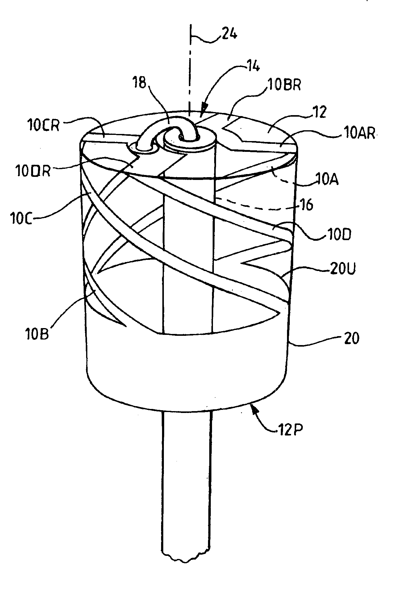
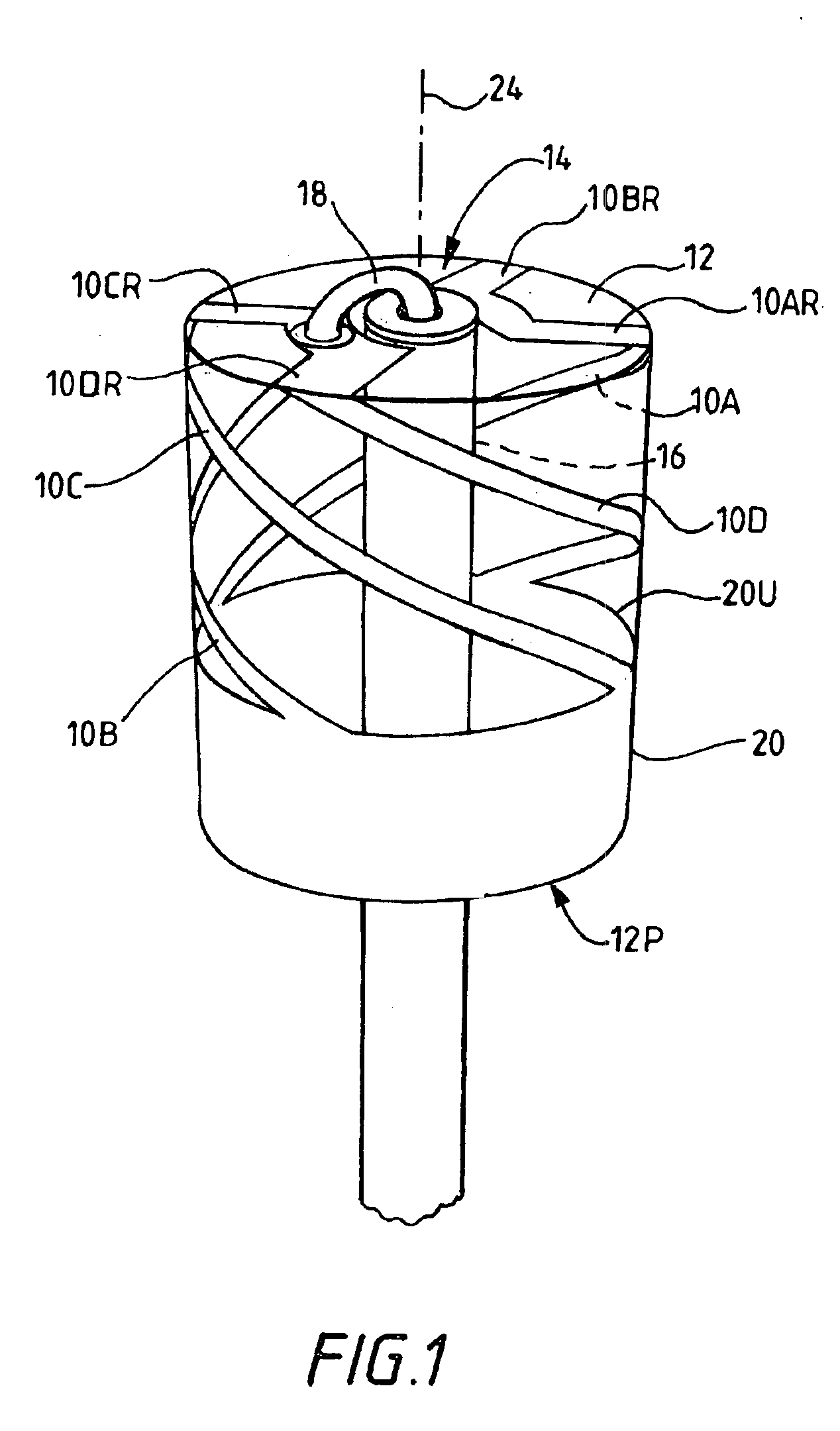
[0018]The quadrifilar antenna described below is similar to that described in the above-mentioned British Patent Application No. GB2310543A, the disclosure of which is incorporated in this specification by reference. The disclosure of the above-mentioned related Application No. GB2292638A is also incorporated in this specification by reference.

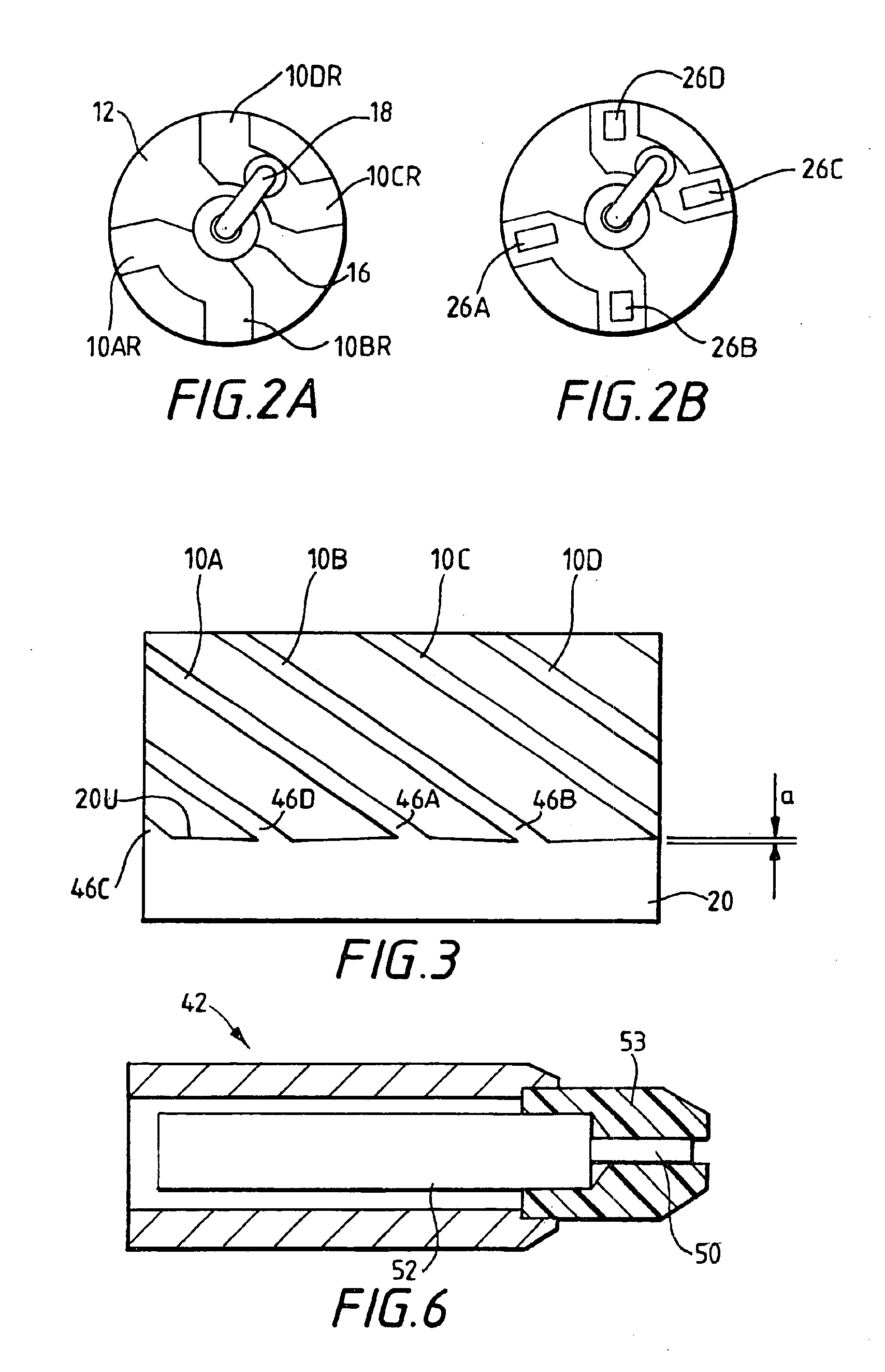
[0019]Referring to FIGS. 1, 2A, 2B and 3, an antenna to which the present invention is applicable has an antenna element structure with four longitudinally extending antenna elements 10A, 10B, 10C, and 10D formed as narrow metallic conductor track portions on the cylindrical outer surface of a ceramic core 12. The core has an axial passage 14 housing a coaxial feeder with an outer screen 16 and an inner conductor 18. The inner conductor 18 and the screen 16 form a feeder structure for connecting a feed line to the antenna elements 10A-10D. The antenna element structure also includes corresponding radial antenna elements 10AR, 10BR, 10CR, 10DR ...


PUM

PropertyMeasurementUnit
frequenciesaaaaaaaaaa
resonant frequencyaaaaaaaaaa
relative dielectric constantaaaaaaaaaa

Abstract

In a method of producing a quadrifilar antenna for circularly polarised radiation at frequencies above 200 MHz, the antenna is tuned by coupling it to a test source, measuring the relative phases and amplitudes of currents at predetermined positions in the individual elements of the antenna by means of probes capacitively coupled to the elements, and laser etching apertures in the elements to increase their inductance, the sizes of the apertures being computed according to the deviation of the measured relative phases from predetermined values.

Description

FIELD OF THE INVENTION[0001]This invention relates to a method of producing an antenna, and primarily to a method of tuning a quadrifilar antenna for circularly polarised radiation at frequencies above 200 MHz. The invention also includes an antenna produced according to the method.BACKGROUND OF THE INVENTION[0002]The backfire quadrifilar antenna is well-known and has particular application in the transmission and reception of circularly polarised signals to or from orbiting satellites. British Patent Application No. 2292638A discloses a miniature quadrifilar antenna having four half-wavelength helical antenna elements in the form of narrow conductive strips plated on the surface of a cylindrical ceramic core. Connecting radial elements on a distal end face of the core connect the helical elements to a coaxial feeder passing axially through the core in a narrow passage. The helical elements are arranged in pairs, the elements of one pair having a greater electrical length than those...

Claims


Application Information

Patent Timeline
Patent Type & Authority Patents(United States)
IPC IPC(8): H01Q11/08H01Q11/00H01Q1/38H01Q9/27H01Q21/26
CPCH01Q11/08Y10T29/4902Y10T29/49004Y10T29/49165Y10T29/49016Y10T29/49156Y10T29/49018H01Q9/27
Inventor LEISTEN, OLIVER PAULWILEMAN, PETER
Owner SARANTEL LTD
Why Eureka
Try Eureka