Continuous production vacuum sintering apparatus and vacuum sintering system adopted to the same

a vacuum sintering and continuous production technology, applied in lighting and heating apparatus, furnace types, furnaces, etc., can solve the problems of low heat efficiency, high cost, and rare adhesion density of cnts and a low conductivity of conventional cnt-fed, so as to increase heat efficiency and manufacturing efficiency, prolong service life, and facilitate inspection

Inactive Publication Date: 2005-05-03
TECO NANOTECH CO LTD
View PDF6 Cites 5 Cited by
  • Summary
  • Abstract
  • Description
  • Claims
  • Application Information

AI Technical Summary

Benefits of technology

[0008]The primary object of the invention is therefore to specify a continuous production vacuum sintering apparatus and a vacuum sintering system adopted to the same. A plurality of vacuum sintering systems with different sintering conditions is arranged on a conveyer unit as a continuous flow process for monitoring sintering quality, production tempo, and manufacturing quantity. Each vacuum sintering system is capable of functioning with both heat conduction and heat radiation with a gradual rate so as to prolong the service life thereof, and to increase heat efficiency and manufacturing efficiency. In addition, the vacuum sintering system prevents rare adhesion density of the CNTs from air disturbance due to an air exhaustion process. The vacuum sintering system is also characteristic of convenient inspection for effectively monitoring product state.

Problems solved by technology

However, because the cathode is heated in a thermal radiation manner, the heating and sinking durations thereof are so long that the manufacturing efficiency thereof cannot increase.
Since an exhaustion valve is provided to be adjacent to the conventional CNT-FED so close that an evaporation rate of the solvent will rise, this results in a low, rare adhesion density of the CNTs and a low conductivity of the conventional CNT-FED thereby.
If an order for multiple conventional CNT-FEDs is received, several furnaces will individually fail with regard to quality management and suffer low manufacturing efficiency, resulting in high costs.

Method used


Image

  • Continuous production vacuum sintering apparatus and vacuum sintering system adopted to the same
  • Continuous production vacuum sintering apparatus and vacuum sintering system adopted to the same
  • Continuous production vacuum sintering apparatus and vacuum sintering system adopted to the same

Examples


Embodiment Construction

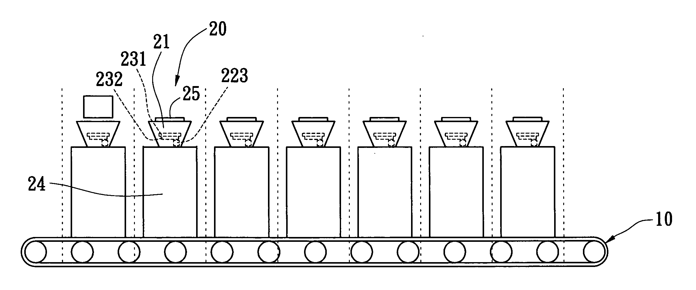
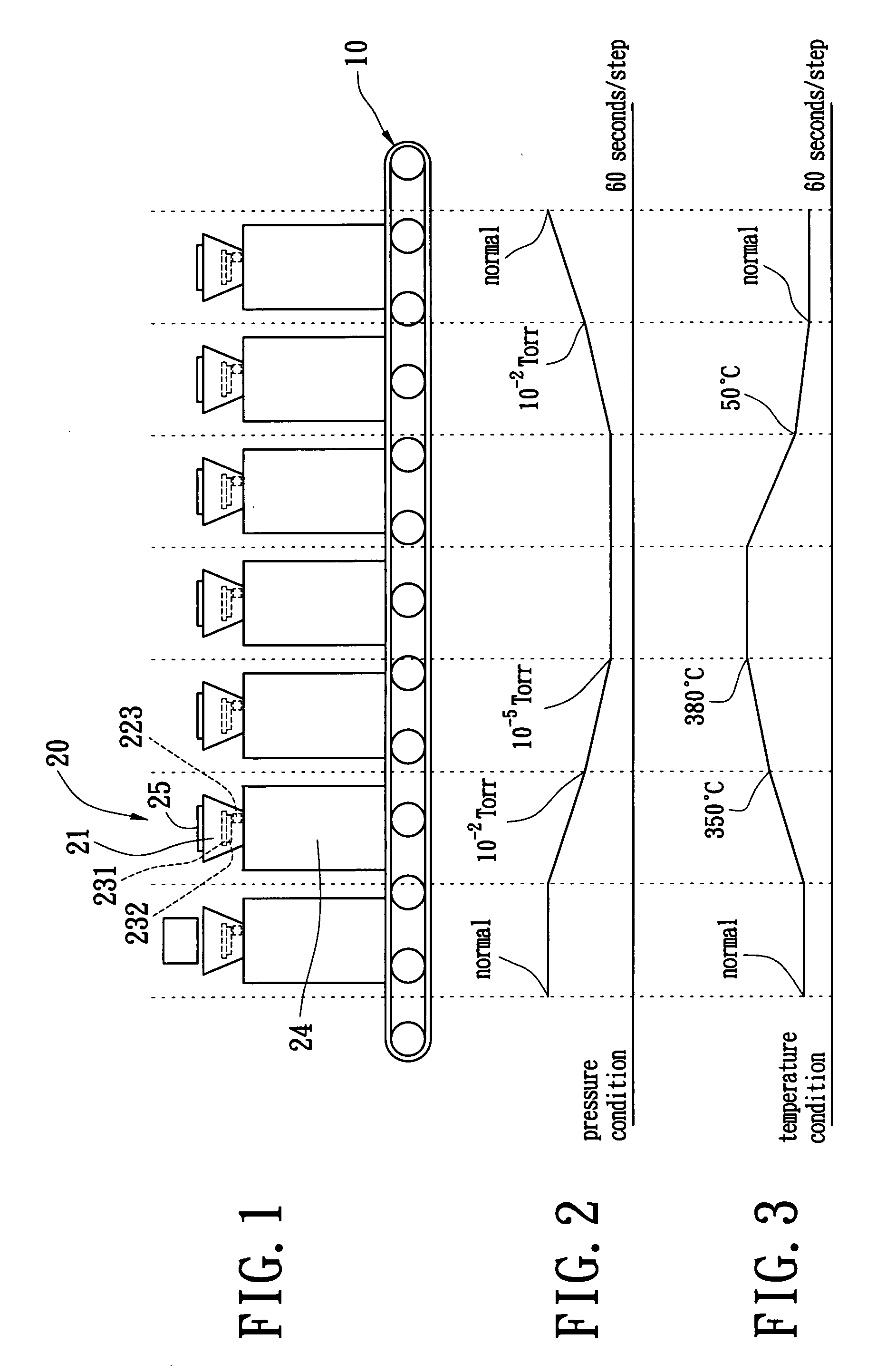
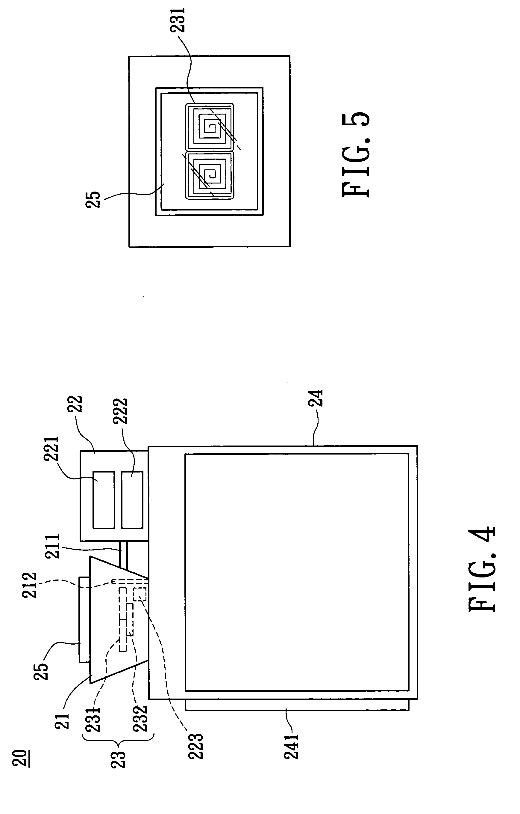
[0017]With respect to FIGS. 1 to 3, the present invention provides a continuous production vacuum sintering apparatus, which includes a conveyer unit 10 and a plurality of vacuum sintering systems 20 individually transferred one by one by the conveyer unit 10. With respect to FIGS. 4 and 5, each of the vacuum sintering systems 20 adopted for an electron emission source includes a sintering furnace 21, a vacuum control unit 22 communicating with the sintering furnace 21 via an exhaustion valve 211, a temperature control unit 23 electrically connecting the sintering furnace 21, and a partition 212 disposed in the sintering furnace 21 and adjacent to the exhaustion valve 211. The temperature control unit 23 includes an infrared radiation ceramic heater 232 and a ceramic plate 231 arranged above the infrared radiation ceramic heater 232. The ceramic plate 231 is capable of spreading and transmitting heat from the infrared radiation ceramic heater 232. The electron emission source (not s...


PUM

PropertyMeasurementUnit
temperatureaaaaaaaaaa
pressureaaaaaaaaaa
temperatureaaaaaaaaaa

Abstract

A continuous production vacuum sintering apparatus has a conveyer unit and a plurality of vacuum sintering systems individually transferred by the conveyer unit. Each of the vacuum sintering systems includes a sintering furnace, a vacuum control unit communicating with the sintering furnace via an exhaustion valve, a temperature control unit electrically connecting the sintering furnace, and a partition disposed in the sintering furnace and adjacent to the exhaustion valve. The vacuum sintering systems correspond to respective sintering steps, each of which continues from a previous one with a predetermined period. The vacuum sintering systems are separate from one another. The respective pressure and temperature conditions provided by the corresponding vacuum sintering systems do not interfere with one another.

Description

BACKGROUND OF THE INVENTION[0001]1. Field of the Invention[0002]The present invention relates to a vacuum sintering apparatus, and particularly relates to a continuous production vacuum sintering apparatus and a vacuum sintering system adopted to the same.[0003]2. Background of the Invention[0004]There are several categories of a flat panel display (FPD), such as, for example a field emission display (FED), a thin film transistor-liquid crystal display (TFT-LCD), a plasma display panel (PDP), an organic electro-luminescence display (OELD), or a reflection-type liquid crystal display (LCD). Thinness, lightness, low power consumption, and portability are the common features among the FPDs mentioned above. The so-called FED has many similarities with conventional cathode ray tubes (CRT). As for the CRT, electrons are accelerated in a vacuum towards phosphors, which then glows. The main difference from the CRT is that the electrons are generated by field emission rather than thermal emi...

Claims


Application Information

Patent Timeline
Patent Type & Authority Patents(United States)
IPC IPC(8): F27B9/00F27B9/04F27B17/00
CPCF27B17/00
Inventor HSIAO, CHUN-YENLI, YU-ANTSAI, JIN-LUNGCHENG, KUEI-WEN
Owner TECO NANOTECH CO LTD
Why Eureka
Try Eureka