300 mm platen and belt configuration

a belt configuration and platen technology, applied in the field of 300 mm, can solve the problems of reducing the yield of wafers, reducing the manufacturing efficiency of further metallization layers, and reducing so as to reduce fluid consumption, improve the non-uniformity of wafers, and reduce the edge effect of wafers.

Inactive Publication Date: 2005-05-03
APPLIED MATERIALS INC
View PDF7 Cites 6 Cited by
  • Summary
  • Abstract
  • Description
  • Claims
  • Application Information

AI Technical Summary

Benefits of technology

[0015]Using the embodiments of the present invention, wafer edge effect can be greatly reduced. Further, embodiments of the present invention advantageously reduce fluid consumption by using only three air pressure zones to provide a positive (out of the platen) airflow, and by using check values to prevent negative (into the platen) airflow. Thus, the embodiments of the present invention improve within wafer nonuniformity. Other aspects and advantages of the invention will become apparent from the following detailed description, taken in conjunction with the accompanying drawings, illustrating by way of example the principles of the invention.

Problems solved by technology

Without planarization, fabrication of further metallization layers becomes substantially more difficult due to the variations in the surface topography.
Hence, large variations in removal rates occur at the wafer edge, resulting in reduced wafer yield.

Method used


Image

  • 300 mm platen and belt configuration
  • 300 mm platen and belt configuration
  • 300 mm platen and belt configuration

Examples


Embodiment Construction

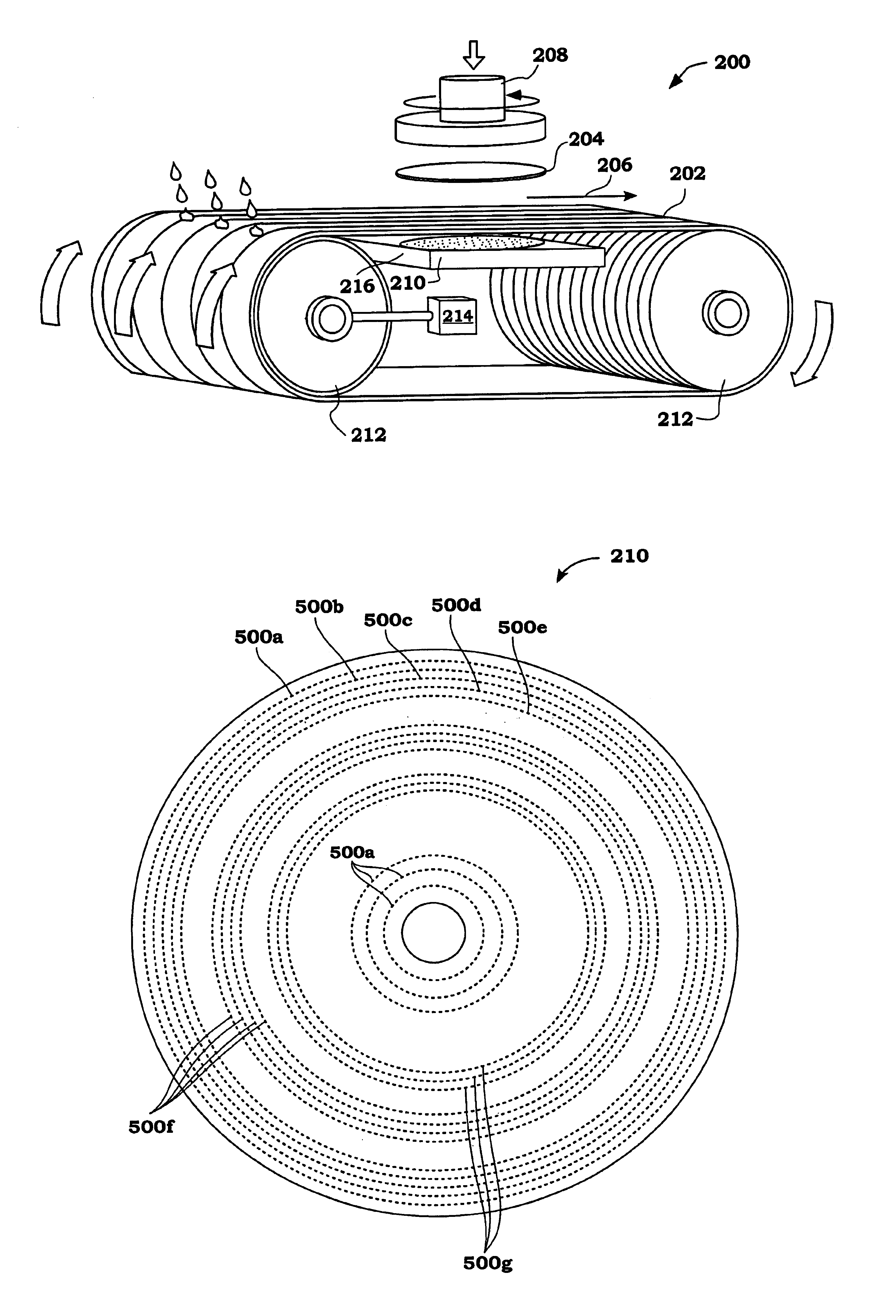
[0028]An invention is disclosed for a 300 millimeter (mm) CMP platen and Belt configuration that greatly reduces edge effect. Broadly speaking, embodiments of the present invention increase belt tension during CMP processing. As a result, platen height and air bearing adjustments can have a greater affect on reducing fast removal rates at the edge of the wafer. In this manner, the embodiments of the present invention improve within wafer nonuniformity. In the following description, numerous specific details are set forth in order to provide a thorough understanding of the present invention. It will be apparent, however, to one skilled in the art that the present invention may be practiced without some or all of these specific details. In other instances, well known process steps have not been described in detail in order not to unnecessarily obscure the present invention.

[0029]FIG. 2 shows a side view of a linear wafer polishing apparatus 200 optimized for reduced edge effect, in ac...


PUM

PropertyMeasurementUnit
heightaaaaaaaaaa
air pressureaaaaaaaaaa

Abstract

An invention is provided for a chemical mechanical planarization apparatus for processing 300 millimeter wafers. The CMP apparatus includes a polishing belt having a belt tension in a range of about 3000 lbs to 4000 lbs. In addition, a platen is disposed below the polishing belt at a positive platen height. The platen includes at least three air pressure zones, with each air pressure zone being capable of providing air pressure to a backside of the polishing belt. The platen can include, for example, eight air pressure zones. In this aspect, a second air pressure zone adjacent to a first outermost air pressure zone provides an air pressure in a range of about 30 psi to 50 psi, such as about 34 psi. In addition, a third air pressure zone a fourth pressure zone can each provide an air pressure in a range of about 4 psi to 13 psi, such as about 7 psi. In this aspect, the remaining air pressure zones can be set to 0 psi, which conserves fluid consumption. Additional fluid consumption reduction can be achieved using a plurality of check values disposed within an air supply system coupled to the platen, wherein the check values prevent negative airflow into the platen.

Description

BACKGROUND OF THE INVENTION[0001]1. Field of the Invention[0002]This invention relates generally to chemical mechanical planarization apparatuses, and more particularly to methods and apparatuses for improved uniformity in chemical mechanical planarization applications using increased belt tension, platen pressure zones, and positive platen height.[0003]2. Description of the Related Art[0004]In the fabrication of semiconductor devices, there is a need to perform chemical mechanical planarization (CMP) operations. Typically, integrated circuit devices are in the form of multi-level structures. At the substrate level, transistor devices having diffusion regions are formed. In subsequent levels, interconnect metallization lines are patterned and electrically connected to the transistor devices to define the desired functional device. As is well known, patterned conductive layers are insulated from other conductive layers by dielectric materials, such as silicon dioxide. As more metalli...

Claims


Application Information

Patent Timeline
Patent Type & Authority Patents(United States)
IPC IPC(8): B24B21/04B24B21/20B24B37/04B24B21/00B24B21/10
CPCB24B21/10B24B37/04B24B21/20
Inventor TAYLOR, TRAVIS ROBERT
Owner APPLIED MATERIALS INC
Why Eureka
Try Eureka