Flashlamp drive circuit

a drive circuit and flashlamp technology, applied in the field of pulsed flashlamps, can solve the problems of increasing the size of the capacitor utilized, prohibitively large, and none of the current circuits are capable of maintaining constant power output, and achieve the effect of low loss

Inactive Publication Date: 2005-05-03
PALOMAR MEDICAL TECH
View PDF20 Cites 89 Cited by
  • Summary
  • Abstract
  • Description
  • Claims
  • Application Information

AI Technical Summary

Benefits of technology

[0008]In accordance with the above, this invention provides, for one aspect thereof, a drive circuit for a pulsed flashlamp which includes a capacitor chargeable to a voltage sufficient, when applied across said lamp, to maintain a desired optical output in arc mode, an inductor connected in series with the lamp, a high-speed semiconductor switch connected to, when off, block discharge of the capacitor and to, when on, permit discharge of the capacitor through the inductor and lamp, a one-way path for current flow from the inductor through the lamp at least when the switch is off, a sensor for current through the lamp and a control operative in response to the sensor for controlling the on/off state of the switch to maintain relative power deviation α=ΔP/Po through the lamp substantially constant over a desired range of average pulsed lamp powers Po. In the equation, power ripple Δ⁢ ⁢P=Pmax-Pmin,Po=Pmax+Pmin2⁢ ⁢and
[0009]The inductor preferably includes an inductance or load coil wound on a magne

Problems solved by technology

However, none of the prior art circuits have the capability of producing quickly changing programmable pulse shapes for the flashlamp output, none of these circuits provide protection for circuit components during switch turn-on transitions, something which is generally required for high powered lamp applications, and none of the current circuits are capable of maintaining constant power output from the lamp, and thus constant lamp intensity, when there are fluctuations in lamp impedance, such fluctuations occurring, and sometimes being substantial, as a result of changes in lamp temperature, and as a result of other factors.
Further, with the possible exception of the “335” patent, in none of these circuits is it feasible to produce flashlamp pulses of longer than several milliseconds, the latter problem resulting from the fact tha

Method used


Image

  • Flashlamp drive circuit
  • Flashlamp drive circuit
  • Flashlamp drive circuit

Examples


Embodiment Construction

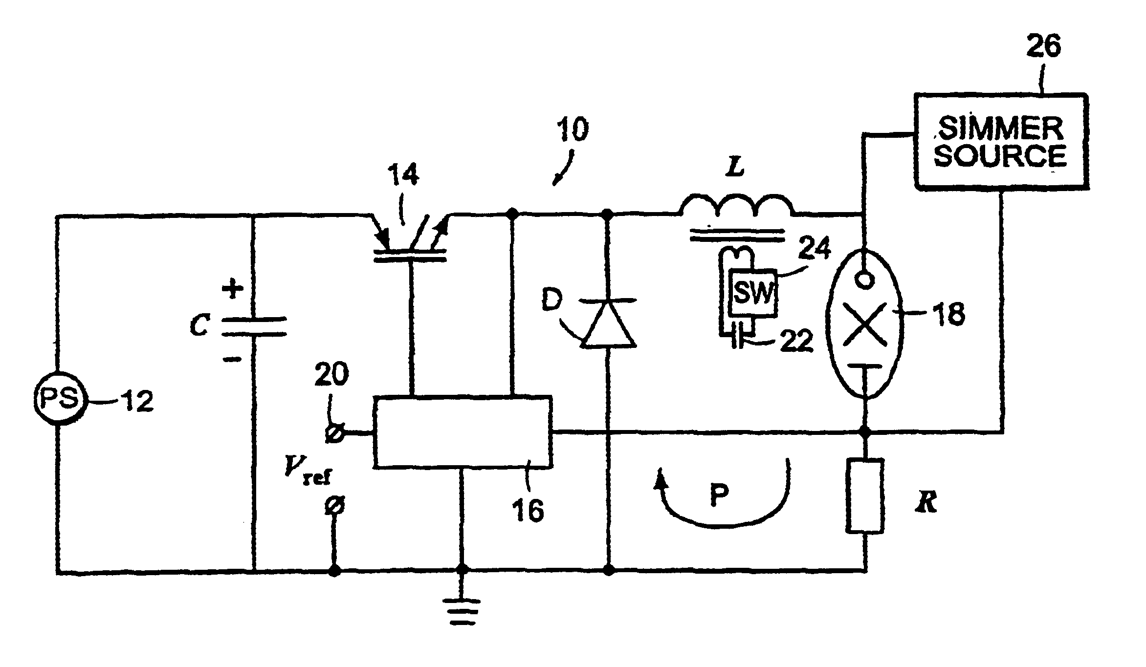
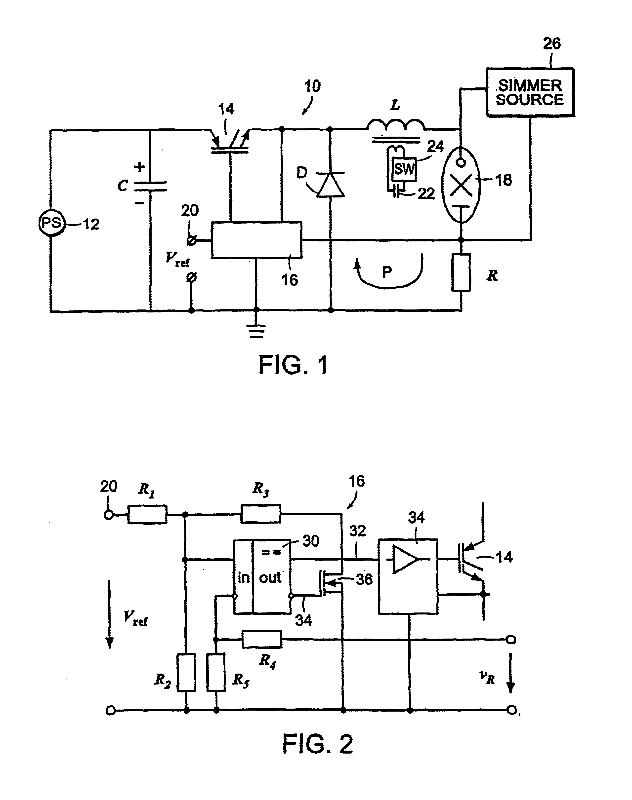
[0018]Referring first to FIG. 1, a pulsed flashlamp drive circuit 10 is shown for an illustrative embodiment of the invention. The circuit includes a capacitor C which is connected to be charged from a suitable power source 12. Power source 12 may be a 120 V, 240 V or other suitable line current, which may be suitably rectified or otherwise processed, may be a battery, or may be some other suitable power source. For illustrative embodiments, charge current from source 12 is only a few amps, for example one to two amps. A standard control circuit (not shown), including a switch, is provided to charge capacitor C to a selected preset voltage E and to prevent overvoltage. Capacitor C discharges through a high speed power switch transistor 14 which is connected to be driven from a control circuit 16, an exemplary such circuit being shown in FIG. 2. The output from switch 14 is applied through an inductor L to one side of pulsed flashlamp 18. The other side of flashlamp 18 is connected t...


PUM


Abstract

The invention provides a power supply or drive circuit for a pulsed flashlamp which utilizes a two-core component having common windings as both an inductor for arc mode drive and for breakdown triggering of the lamp. Discharge of a capacitor through the inductor and lamp is controlled by a high-speed semiconductor switch which is turned on and off by a suitable control, current flowing from the inductor through a one-way path including the lamp when the switch is off. The control maintains the ratio of the power variation through the lamp to the average power through the lamp substantially constant. The controls may also be utilized to control output pulse shape. Novel protective features are also provided for circuit components during turn on periods for the switch.

Description

CROSS-REFERENCE TO RELATED APPLICATIONS[0001]This invention is a continuation-in-part of U.S. patent application Ser. No. 10 / 267,610, filed Oct. 9, 2002, entitled “Flashlamp Drive Circuit” by Mikhail Inochkin, Vycheslav V. Togatov, and Peter O. Gnatyuk, which is a continuation of U.S. patent application Ser. No. 09 / 797,501, filed Mar. 1, 2001 now abandoned, entitled “Flashlamp Drive Circuit” by Mikhail Inochkin, Vycheslav V. Togatov, and Peter O. Gnatyuk, all of which are incorporated herein by reference in their entirety.FIELD OF THE INVENTION[0002]This invention relates to pulsed flashlamps and more particularly to improved drive circuits for such flashlamps.BACKGROUND OF THE INVENTION[0003]Pulsed flashlamps, and in particular Xe filled flashlamps, are used in a variety of applications, including to pump various gas or other laser devices, in various photo, copying, optical detection and optical ranging applications, in cosmetology and in various dermatology and other medical appl...

Claims


Application Information

Patent Timeline
IPC IPC(8): H05B41/30A61B18/18H05B41/34
CPCH05B41/34H05B41/30A61B2018/1807
Inventor INOCHKIN, MIKHAILTOGATOV, VYCHESLAV V.GNATYUK, PETER O.
Owner PALOMAR MEDICAL TECH
Why Eureka
Try Eureka