Multi-cascode transistors

a transistor and cascode technology, applied in the direction of pulse technique, amplifiers with multiple amplifiers, emergency protective arrangements for limiting excess voltage/current, etc., can solve the problems of low breakdown voltage of transistors, operating conditions above what these devices can support, and applications requiring a high power output to a high impedance load,

Inactive Publication Date: 2005-05-03
CALIFORNIA INST OF TECH
View PDF10 Cites 72 Cited by
  • Summary
  • Abstract
  • Description
  • Claims
  • Application Information

AI Technical Summary

Benefits of technology

[0013]Those skilled in the art will appreciate the advantages and superior features of the invention together with other important aspects thereof on reading the detailed description that follows in conjunction with the drawings.
[0014]FIGS. 1a and 1B are diagrams of cascode circuits for providing a cascode topology using three or more transistors in accordance with an exemplary embodiment of the present invention;
[0015]FIG. 2 is a graph showing an example of total VDS varying as a function of time from zero to a peak value that consists of five components, namely, VDS1 through VDS5;
[0016]FIGS. 3a and 3b show cascode circuits with nonlinear gate or base voltages, in accordance with an exemplary embodiment of the present invention;
[0017]FIG. 4 shows an exemplary voltage waveform VG1 as applied to an input of cascode transistors;
[0018]FIGS. 5a and 5b show cascode circuits with drain or source controlled gate voltages in accordance with an exemplary embodiment of the present invention;

Problems solved by technology

The low breakdown voltage of transistors is problematic for power applications.
Nevertheless, certain applications demand the use of a high voltage supply resulting in operating conditions above what these devices can support.
Applications requiring a high power output to a high impedance load and other applications cannot be implemented if low breakdown voltage transistors are used in a conventional way.
A conventional cascode arrangement with two transistors connected in series presents several limitations.
First, the maximum voltage allowable between the collector to emitter or the drain to source is limited to twice the voltage that an individual transistor can support.
Higher voltage cannot be applied without risking voltage breakdown.
Second, if the gate or base voltage of the second transistor is held constant, a DC voltage between the collector and the base or the base and the emitter of a BJT, or between the drain and the gate or the gate and the source of a FET transistor, can cause a voltage breakdown.
This capacitor will occupy an undesired large area increasing the cost of the integrated circuit and making the layout of the circuit more difficult.
These limitations restrict the use of conventional cascode topologies to the applications that require an output voltage lower than twice the breakdown voltage of the individual transistor.

Method used


Image

  • Multi-cascode transistors
  • Multi-cascode transistors
  • Multi-cascode transistors

Examples


Embodiment Construction

[0025]In the description that follows like parts are marked throughout the specification and drawings with the same reference numerals, respectively. The drawing figures are not necessarily to scale and certain features may be shown in somewhat generalized or schematic form in the interest of clarity and conciseness.

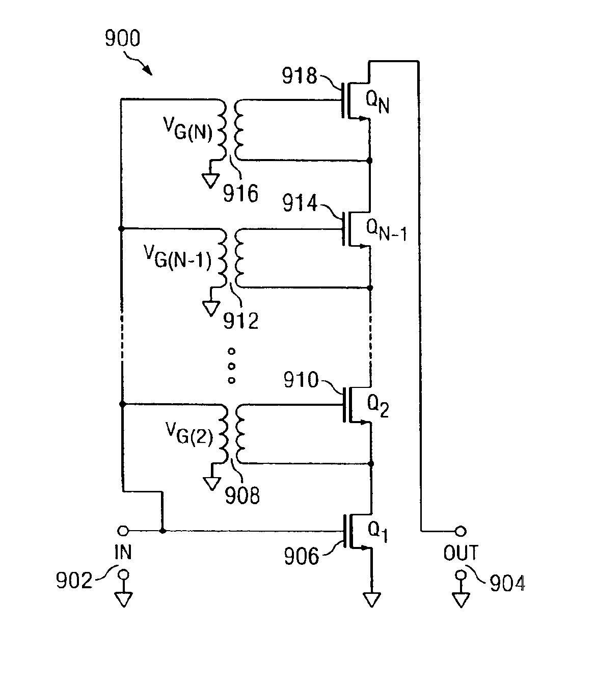
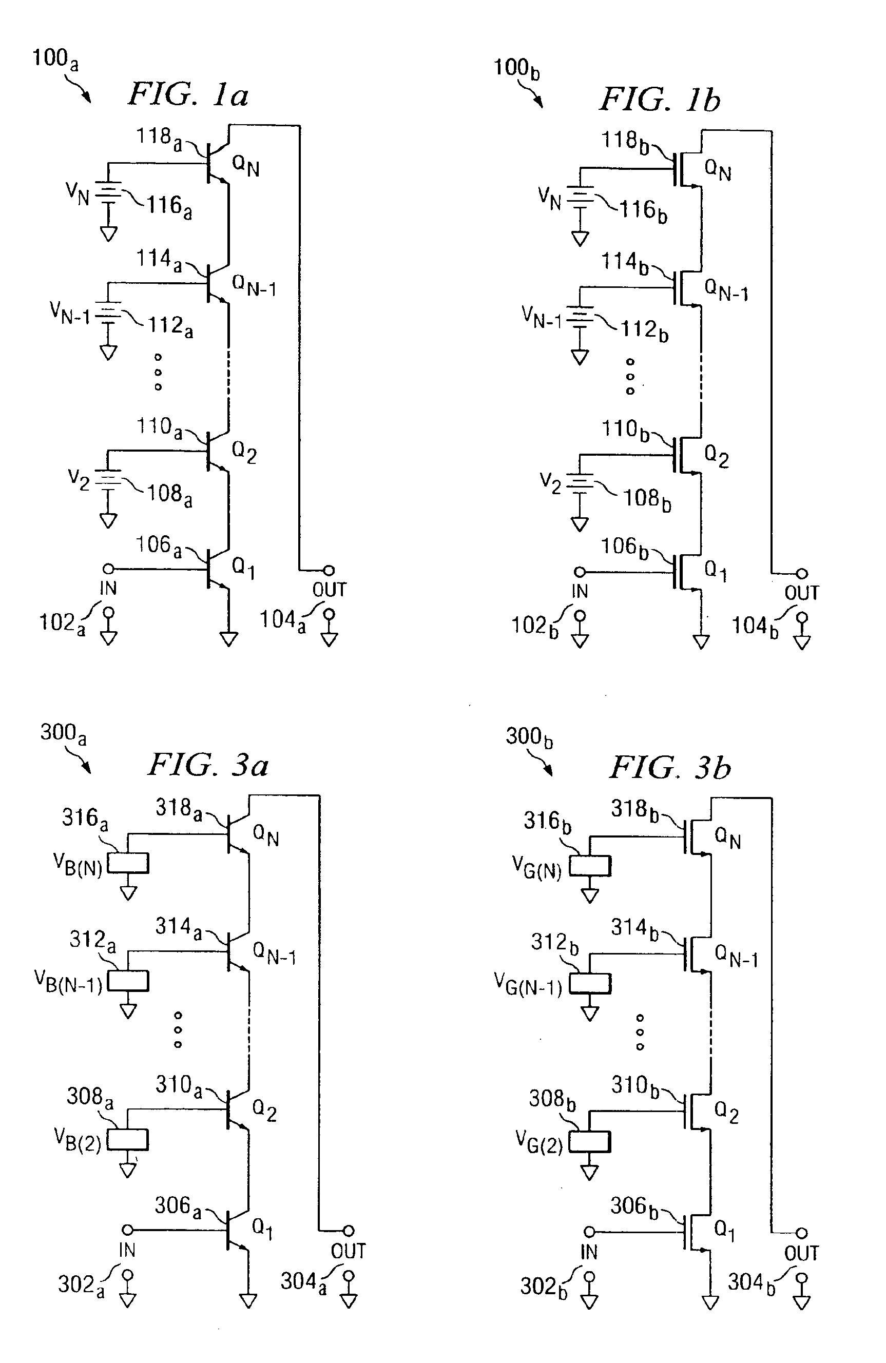
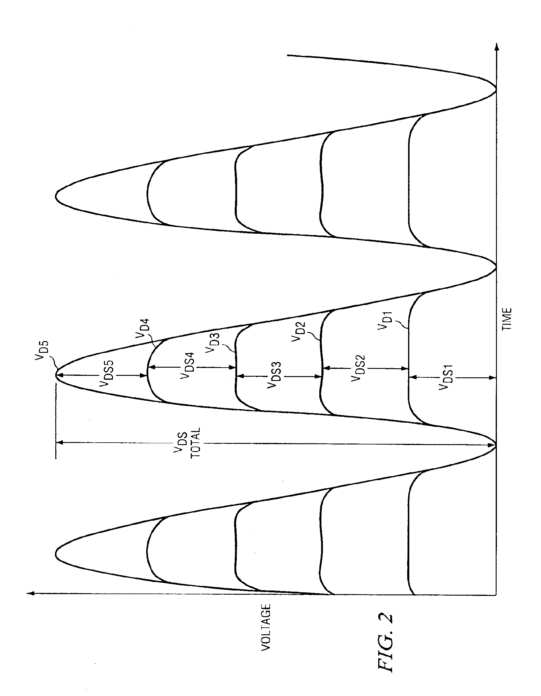
[0026]FIGS. 1a and 1B are diagrams of cascode circuits 100a and 100b for providing a cascode topology using three or more transistors in accordance with an exemplary embodiment of the present invention. Cascode circuits 100a and 100b allow the peak voltage applied between the drain or collector of a top-most transistor and the source or emitter of the bottom-most transistor to be divided amongst all transistors, so as to prevent voltage breakdown of one or more transistor.

[0027]Cascode circuit 100a includes input 102a and output 104a, and cascode circuit 100b includes input 102b and output 104b. For cascode circuit 100a, BJT transistor 106a functions as Q1, the signal pr...


PUM


Abstract

A cascode circuit with improved withstand voltage is provided. The cascode circuit includes three or more transistors, such as MOSFET transistors. Each transistor has a control terminal, such as a gate, and two conduction terminals, such as a drain and a source. The conduction terminals are coupled in series between two output terminals, such as where the drain of each transistor is coupled to the source of another transistor. A signal input is provided to the gate for the first transistor. Two or more control voltage sources, such as DC bias voltages, are provided to the gate of the remaining transistors. The DC bias voltages are selected so as to maintain the voltage across each transistor to a level below a breakdown voltage level.

Description

CROSS-REFERENCE TO RELATED APPLICATIONS[0001]This application claims priority to provisional U.S. patent application Ser. No. 60 / 363,483, filed Mar. 11, 2002, which is expressly incorporated by reference for all purposes.FIELD OF THE INVENTION[0002]The present invention pertains to the field of cascode transistor architectures. More specifically, the invention relates to multi-cascode transistors that provide optimized breakdown voltage for power transistors.BACKGROUND OF THE INVENTION[0003]The low breakdown voltage of transistors is problematic for power applications. High frequency transistors such as but not limited to submicron CMOS transistors, silicon on insulator (CMOS-SOI) transistors, silicon (Si) transistors, silicon germanium (SiGe) transistors, and SiGe heterojunction bipolar transistors (HBT) support maximum voltages ranging from ten volts to four volts or even lower between the drain to source, drain to gate, collector to emitter, or collector to base. Nevertheless, ce...

Claims


Application Information

Patent Timeline
Patent Type & Authority Patents(United States)
IPC IPC(8): H03F3/42H03F1/22H03F3/45
CPCH03F1/22H03F1/223H03F1/226H03F3/423H03F3/45179H03F3/42H03F2203/45394H03F2203/45301
Inventor HAJIMIRI, SEYED-ALIKEE, SCOTT D.AOKI, ICHIRI
Owner CALIFORNIA INST OF TECH
Why Eureka
Try Eureka