Position control apparatus and position control method

a technology of position control and position control, applied in the direction of program control, electric controller, instruments, etc., can solve the problem of backlash elimination kicks, and achieve the effect of suppressing tracking errors

Inactive Publication Date: 2005-05-03
TOSHIBA MASCH CO LTD
View PDF7 Cites 18 Cited by
  • Summary
  • Abstract
  • Description
  • Claims
  • Application Information

AI Technical Summary

Benefits of technology

[0016]An object of the present invention is to provide a position control apparatus and method capable of suppressing tracking error from a variable position reference occurring when a control object positioned via a transmission mechanism with mechanical transmission error resumes movement from a state stopped at a target position.

Problems solved by technology

If reversal of the feed direction in the variable position reference is detected from this state, however, backlash elimination kicks in and the control object ends up deviating from the target position for an instant.

Method used


Image

  • Position control apparatus and position control method
  • Position control apparatus and position control method
  • Position control apparatus and position control method

Examples


first embodiment

[0033

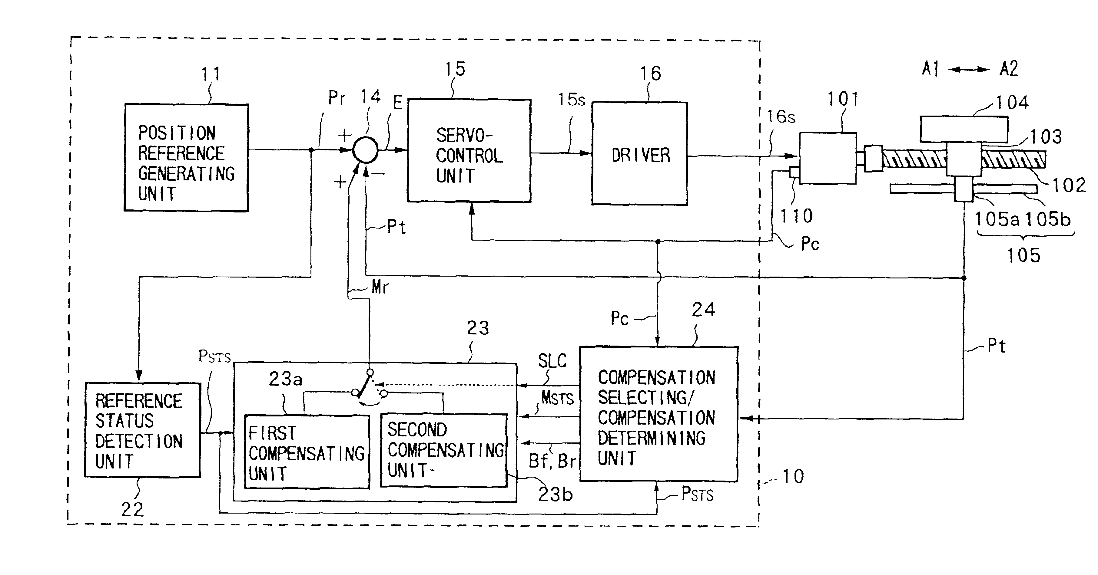
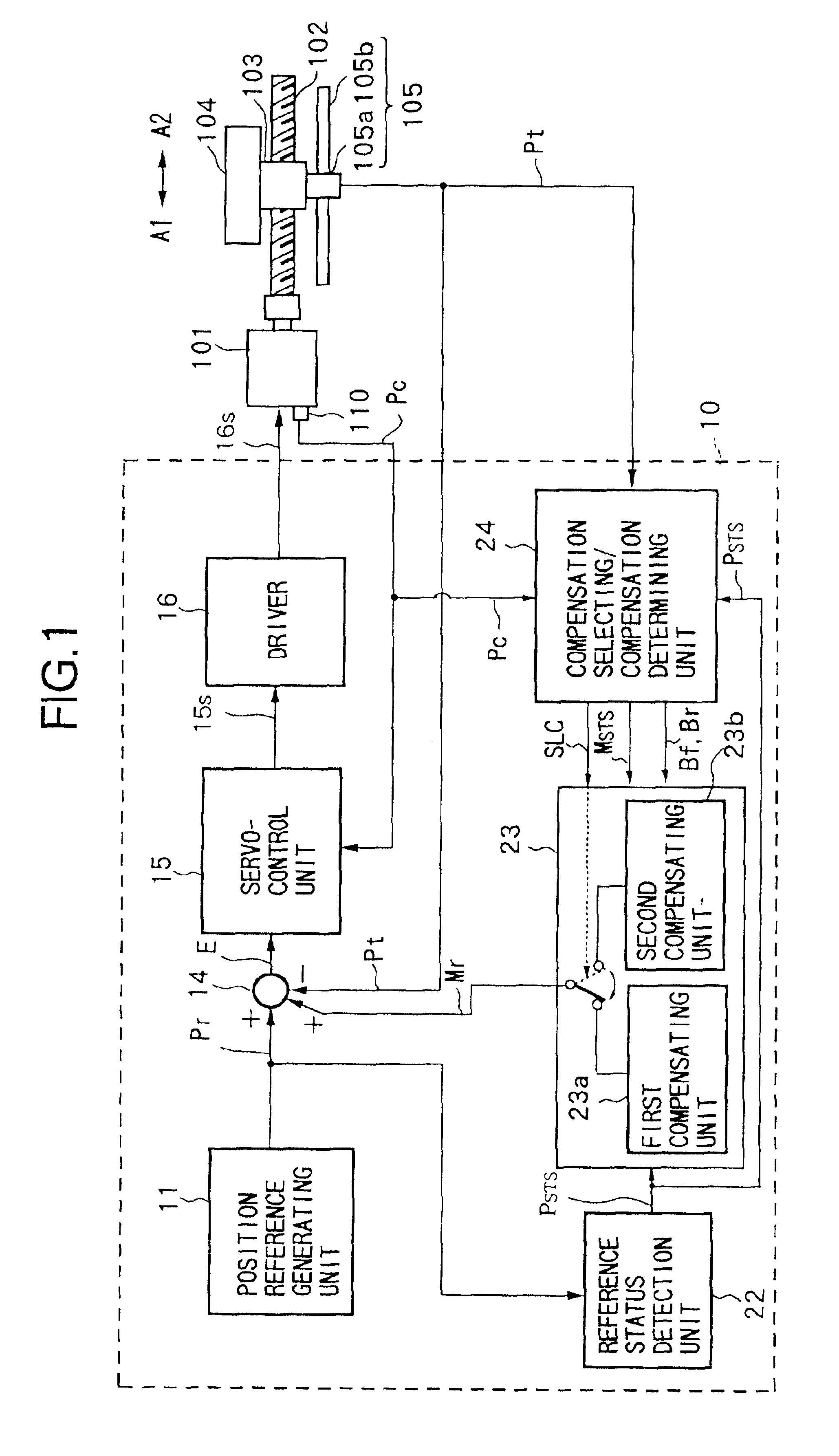
[0034]FIG. 1 shows the configuration of a position control system according to a first embodiment of the present invention.

[0035]In FIG. 1, the position control system 1 is provided with a position control apparatus 10, a servomotor 101, a rotational position detector 110 of an optical or magnetic type connected to the servomotor 101, a ball screw shaft 102 connected to the servomotor 101 with a threaded part at the outer periphery, a movable member 103 having a threaded bore engaged with the threaded part of the ball screw shaft 102, a table 104 connected to the movable member 103 and held by a guide member (not shown) so as to be able to move in the axial directions of the ball shaft 102 shown by arrows A1 and A2, and a linear scale 105 constructed by a detector 105a affixed to the table 104 and a scale 105b extending along the directions A1 and A2.

[0036]In the claimed invention, the table 104 corresponds to the control object or controlled system, while the linear scale 105 ...

second embodiment

[0142

[0143]FIG. 7 is a view of the configuration of a position control system according to a second embodiment of the present invention.

[0144]In FIG. 7, the same reference numerals are used for parts the same as in the above described embodiment.

[0145]The difference between the position control system according to the present embodiment and the position control system according to the first embodiment is a control deviation generating unit 210 in the position control apparatus 200 according to the present embodiment.

[0146]Further, in the position control system 300 according to the present embodiment, the detected rotational position signal Pc of an optical or electromagnetic type rotational position sensor 110 mounted to the servomotor 101 is fed back to the control deviation generating unit 210.

[0147]The control deviation generating unit 210 has a converting unit 216, a position error calculating unit 215, a filtering unit 214, a position calculating unit 212, subtracting unit 213...


PUM


Abstract

A position control apparatus and method has been devised which provides for an improved means of suppressing tracking error from a variable position reference occurring when a control object positioned via a transmission mechanism with mechanical transmission error resumes movement from a state stopped at a target position. A selection between two alternative tracking error compensating means within the control apparatus is made based on whether the detected position of the control object changes in a period after the control object stops and before the variable position reference is input again to a control deviation generating unit.

Description

BACKGROUND OF THE INVENTION[0001]1. Field of the Invention[0002]The present invention relates to an apparatus and method for controlling a position of a control object in a numerical control (NC) machine tool or other machine.[0003]2. Description of the Related Art[0004]Positional control of a control object such as a work table and a work cutting tool in an NC machine tool is generally achieved by controlling rotation of a servomotor connected to the control object via a transmission mechanism constructed for example by a rack and pinion or a ball screw and nut.[0005]As methods for positional control of a control object, a semi-closed-loop control system, a full-closed-loop control system, and a hybrid control system are known.[0006]In the semi-closed-loop control system, the servo control system is constructed to detect the rotational position of the servomotor by a rotary encoder or other detector, convert the detected rotational position of the servomotor to the position of the ...

Claims


Application Information

Patent Timeline
Patent Type & Authority Patents(United States)
IPC IPC(8): G05B19/404G05B11/01G05D3/12G06F19/00H02P5/00H02P29/00H02P29/40
CPCG05B19/404G05B2219/41045G05B2219/41041
Inventor SHIBA, KAZUHIROHAMAMURA, MINORUFUJITA, JUN
Owner TOSHIBA MASCH CO LTD
Why Eureka
Try Eureka