
Fuel supply system of an internal combustion engine

a fuel supply system and internal combustion engine technology, applied in the direction of electrical control, lighting support devices, lighting and heating apparatus, etc., can solve the problem of aconsiderable shortening of the startup process

Inactive Publication Date: 2005-05-10
ROBERT BOSCH GMBH
View PDF32 Cites 88 Cited by
  • Summary
  • Abstract
  • Description
  • Claims
  • Application Information

AI Technical Summary

Benefits of technology

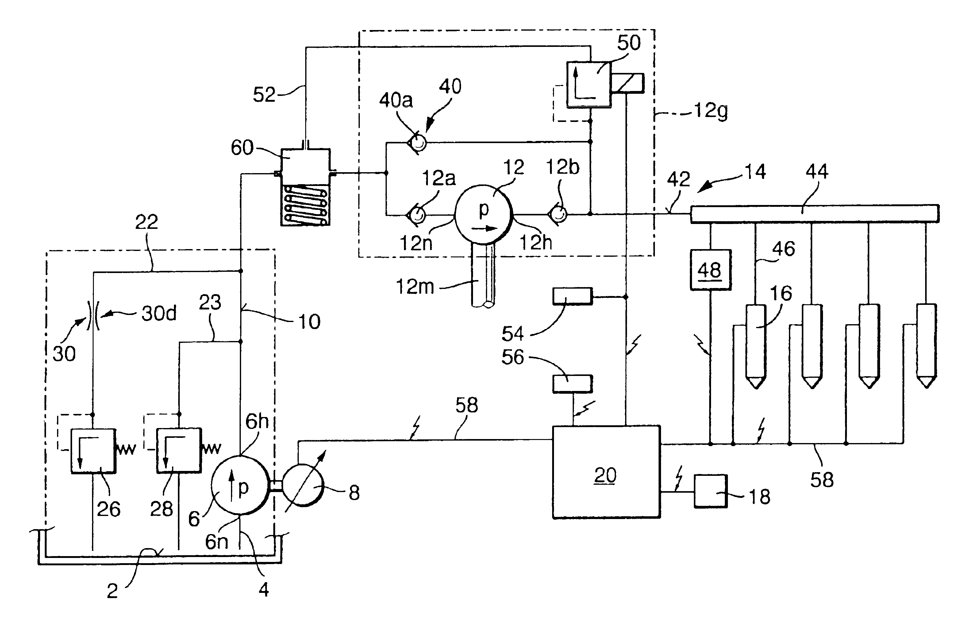
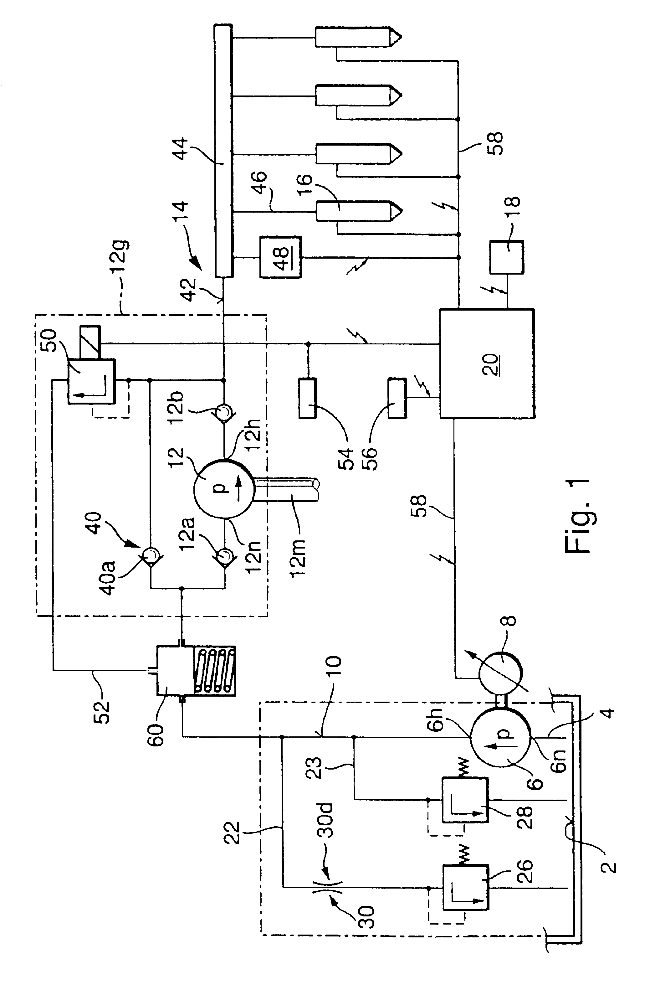
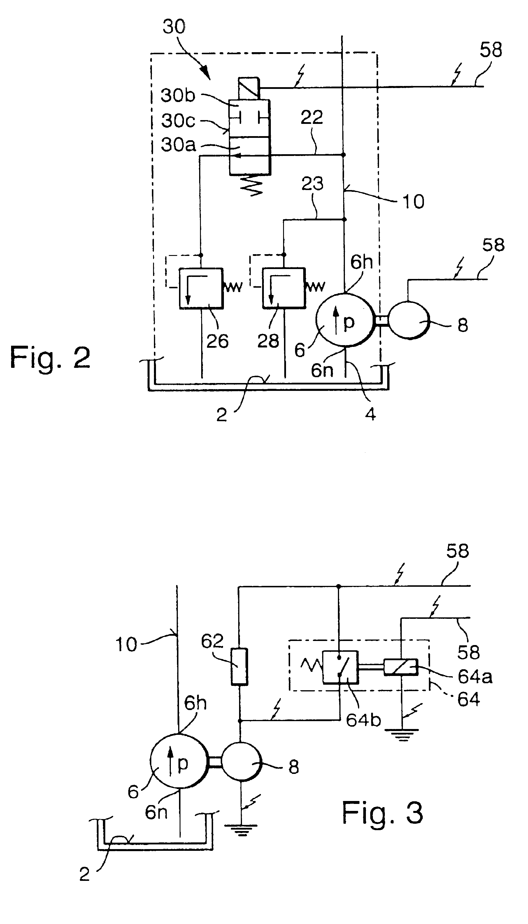
[0004]The fuel supply system according to the invention has an advantage over the prior art that the quantity of fuel delivered by the first fuel pump can be adapted as needed to the currently prevailing operating conditions of the engine.
[0005]In particular, it is advantageously possible that during the startup of the engine, the delivery capacity of the first fuel pump is increased, by means of which the startup time of the engine can be significantly reduced.
[0006]Due to the increased delivery capacity during the startup of the engine, a possible vapor bubble inside the system can be very rapidly eliminated, which leads to a considerable shortening of the startup process.

Problems solved by technology

Due to the increased delivery capacity during the startup of the engine, a possible vapor bubble inside the system can be very rapidly eliminated, which leads to a considerable shortening of the startup process.

Method used


Image

  • Fuel supply system of an internal combustion engine
  • Fuel supply system of an internal combustion engine
  • Fuel supply system of an internal combustion engine

Examples


Embodiment Construction

[0024]The fuel supply system according to the invention, for metering fuel for an internal combustion engine, can be used in different types of engines. The engine, for example, is a gasoline engine with an external or internal mixture formation and externally supplied ignition, wherein the engine can be provided with a reciprocating piston (reciprocating piston engine) or with a rotatably supported piston (rotary piston engine). The engine can, for example, also be a hybrid engine. In this engine with stratified charge, the fuel / air mixture in the combustion chamber is enriched in the vicinity of a spark plug until a reliable ignition is assured, but the combustion occurs in the center where there is a very lean mixture.

[0025]The gas exchange in the combustion chamber can, for example, take place in accordance with the four-stroke process or in accordance with the two-stroke process. Gas exchange valves (inlet valves and outlet valves) can be provided in a known manner for controll...


PUM


Abstract

In fuel supply systems with two fuel pumps connected in series and fuel valves that inject directly into the combustion chamber, there have been occasional problems. The proposal is made that in order to eliminate these problems, the first fuel pump operates with increased delivery capacity, particularly during the startup process and in the event of high fuel temperature. The fuel supply system is provided for an internal combustion engine of a vehicle.

Description

BACKGROUND OF THE INVENTION[0001]The invention is based on a fuel supply system for delivering fuel for an internal combustion engine set forth hereinafter.[0002]Up till now, there have been fuel supply systems in which a first fuel pump delivers fuel from a fuel tank to a second fuel pump by way of a fuel connection. For its part, the second fuel pump delivers the fuel via a pressure line to at least one fuel valve. Normally, the number of fuel valves is the same as the number of cylinders of the engine. The fuel supply system can be designed so that the fuel valve injects the fuel directly into a combustion chamber of the engine. During operation of this fuel supply system, a high pressure is required in the pressure line leading to the fuel valve. For safety reasons, and due to leaks of the fuel valve into the combustion chamber which can never be completely prevented, it is useful after the engine is shut off to either completely or at least largely reduce the pressure in the fu...

Claims


Application Information

Patent Timeline
Patent Type & Authority Patents(United States)
IPC IPC(8): F02M63/02F02D41/06F02M63/00F02D41/38F02D41/30F02M37/08F02M37/18F02M37/00F02M37/20
CPCF02D41/062F02D41/3082F02D41/3809F02D41/3854F02M63/0245F02M37/08F02M37/18F02D41/3029F02D2200/0606F02D2250/02F02D2041/389F21V21/02F21V1/12F21V17/14
Inventor REMBOLD, HELMUTFRANK, KURT
Owner ROBERT BOSCH GMBH
Learn More