
Gas purification system with an integrated hydrogen sorption and filter assembly

a technology of hydrogen sorption and filter assembly, which is applied in the direction of nitrogen purification/separation, separation process, filtration separation, etc., can solve the problems of lagging regenerative heat exchanger in prior art purifiers, bulky bulky gas purification systems, etc., to reduce cost, facilitate maintenance and manufacture, and reduce the effect of components

Inactive Publication Date: 2005-05-10
ENTEGRIS GP INC
View PDF18 Cites 43 Cited by
  • Summary
  • Abstract
  • Description
  • Claims
  • Application Information

AI Technical Summary

Benefits of technology

[0009]The present invention fulfills the needs over the prior art. The present invention provides a gas purification system with improved efficiency, simpler construction, cost reductions, form factor improvements, and increased durability.
[0010]The present invention provides cost and form factor improvements through fewer components overall and through utilizing multiple integrated components. Prior art gas purification systems are more bulky and complicated.
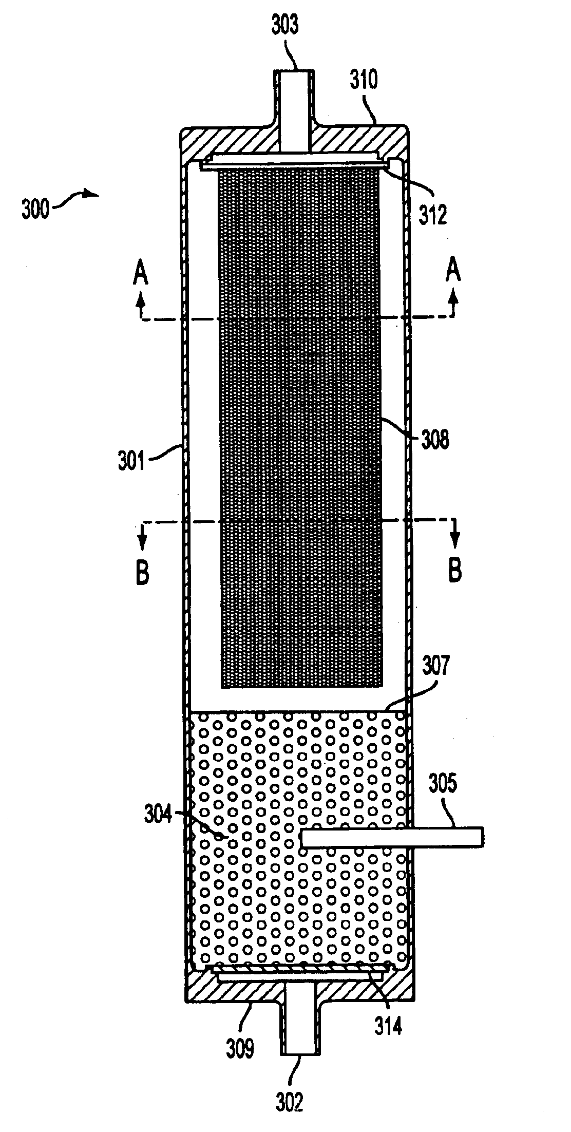
[0013]Prior art gas purification systems also utilized discrete residual hydrogen sorption and particle filtering components. The present invention integrates the two discrete components into one integrated hydrogen sorption and particle filter assembly. The integrated hydrogen sorption and particle filter assembly is also capable of operating at higher temperatures. This eases maintenance and manufacture.
[0014]The resulting gas purification system is simpler through utilizing fewer components, smaller by utilizing fewer and integrated components, and reduced cost through fewer components, smaller components and through reduced manufacturing labor requirements.

Problems solved by technology

Prior art gas purification systems are more bulky and complicated.
Prior art purifiers lacked a regenerative heat exchanger.

Method used


Image

  • Gas purification system with an integrated hydrogen sorption and filter assembly
  • Gas purification system with an integrated hydrogen sorption and filter assembly
  • Gas purification system with an integrated hydrogen sorption and filter assembly

Examples


Embodiment Construction

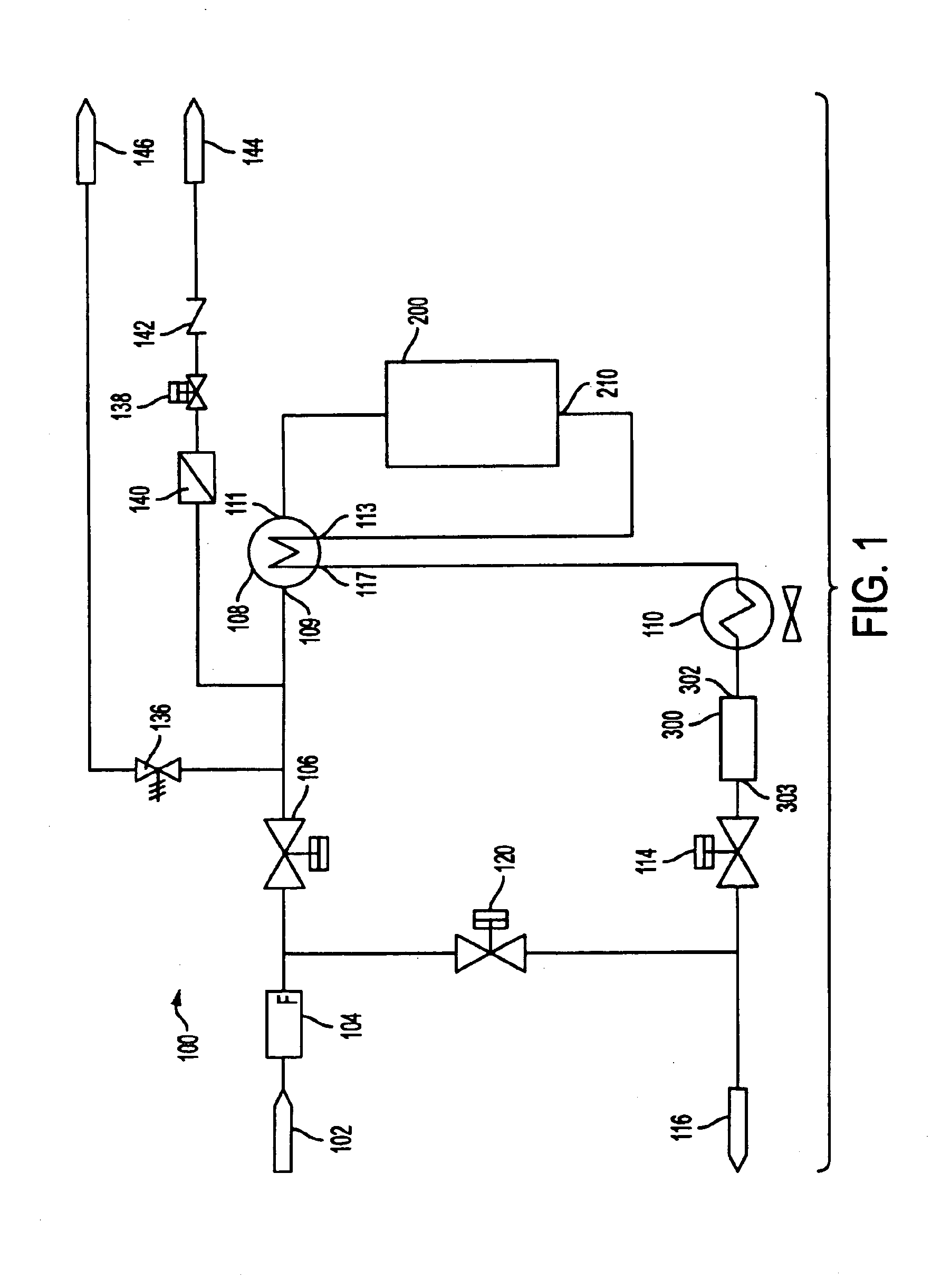
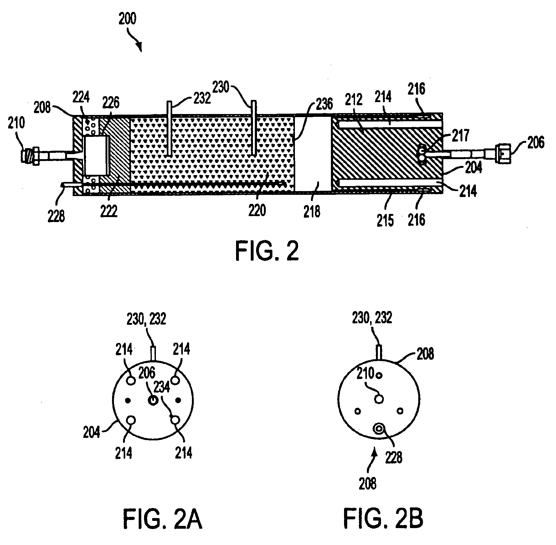
[0027]FIG. 1 schematically illustrates a gas purification system 100 in accordance with one embodiment of the present invention. The gas purification system 100 includes an inlet 102, an optional mass flow meter 104, a first solenoid activated valve 106, a first heat exchanger assembly 108, a heated getter vessel 200, a second heat exchange assembly 110, an integrated hydrogen sorption and particle filter assembly 300, a second solenoid activated valve 114, and an outlet 116. The system 100 also includes a bypass valve 120, an inlet option valve 130, an outlet option valve 132, an outlet sample valve 134, a pressure relief valve 136, a vent valve 138, a vent line filter 140, a vent line check valve 142, a vent outlet 144, and a relief line vent 146.

[0028]The interior surfaces of the gas purification system which may be contacted by a gas should be clean and well-polished. For example, the interior surfaces of all of the connecting tubing, the valves, and the various gas handling ass...


PUM

PropertyMeasurementUnit
Lengthaaaaaaaaaa
Angleaaaaaaaaaa
Temperatureaaaaaaaaaa

Abstract

The present invention provides a gas purification system with improved efficiency, simpler construction, cost reductions, form factor improvements, and increased durability. The present invention provides cost and form factor improvements through fewer components overall and through utilizing multiple integrated components. Prior art gas purification systems are more bulky and complicated. The present invention achieves increased thermal efficiency through utilization of a regenerative heat exchanger to recapture a portion of the heat energy transferred to the gas during the purification process. Prior art purifiers lacked a regenerative heat exchanger. The present invention integrates the two components into one integrated heater and purification vessel assembly. The present invention integrates the two discrete components into one integrated hydrogen sorption and particle filter assembly. The integrated hydrogen sorption and particle filter assembly is also capable of operating at higher temperatures. This eases maintenance and manufacture. The resulting gas purification system is simpler through utilizing fewer components, smaller by utilizing fewer and integrated components, and reduced cost through fewer components, smaller components and through reduced manufacture labor requirements.

Description

CROSS REFERENCE TO RELATED APPLICATIONS[0001]The present application claims benefit pursuant to 35 U.S.C. § 120 and is a continuation of U.S. application Ser. No. 09 / 614,649 entitled “Gas Purification System With An Integrated Hydrogen Sorption And Filter Assembly,” filed Jul. 12, 2000 and issued as U.S. Pat. No. 6,733,571 B1 on May 11, 2004, which claims priority under 35 U.S.C. § 119(e) from U.S. Provisional Application No. 60 / 143,377, filed Jul. 12, 1999, both of which are incorporated herein in their entirety by reference.BACKGROUND OF THE INVENTION[0002]The invention relates generally to gas purification systems for the purification of noble gases and nitrogen. In particular, the method of purification consists of heating an impure gas, contacting the impure gas with an impurity sorption material to produce a purified gas, cooling the purified gas to a temperature less than about 100° C., and contacting the purified gas with a hydrogen sorption material to remove residual hydro...

Claims


Application Information

Patent Timeline
IPC IPC(8): B01D46/00B01D53/04C01B21/00C01B21/04C01B23/00B01D53/02
CPCB01D46/2403B01D46/448B01D53/04B01D53/0423C01B21/0433C01B21/0483C01B23/0036C01B23/0084B01D46/4272C01B2210/0053B01D53/0438B01D53/0454B01D2253/10B01D2253/112B01D2253/25B01D2253/304B01D2253/342B01D2256/10B01D2256/18B01D2257/108B01D2258/0216B01D2259/40001B01D2259/40009B01D2259/40088B01D2259/40098B01D2259/402B01D2259/65B01D2267/00
Inventor ARQUIN, PIERRE J.LINDAHL, NELS W.CANAAN, MARK A.
Owner ENTEGRIS GP INC
Learn More