Light emitting element material

a technology light emitting elements, which is applied in the direction of discharge tube luminescnet screens, natural mineral layered products, etc., can solve the problems of troublesome operation of light emitting layers, and inability to meet the requirements of light emitting elements, etc., to achieve high color purity

Inactive Publication Date: 2005-05-10
FUJIFILM CORP
View PDF8 Cites 2 Cited by
  • Summary
  • Abstract
  • Description
  • Claims
  • Application Information

AI Technical Summary

Benefits of technology

[0009]A first object of the present invention is to provide a red light emitting element material with high color purity and a light emitting element using the red light emitting element material.

Problems solved by technology

With red light emission, it is difficult to use a single fluorescent dye as a light emitting layer due to significant density quenching.
However, there is a problem with this method that, in a case in which an element on which a dye has been doped by vapor deposition is produced, a host material and a very small quantity of the fluorescent dye must be vapor-deposited together so that the operation thereof is troublesome.
Further, inconsistency in performance of the manufactured organic light emitting element is liable to occur.
However, an element which is produced by a conventional coating method is inferior to an element which is produced by a vapor deposition method in terms of light emission luminance and light emission efficiency.
Light emission with high luminance and high efficiency is a significant issue.
However, with the light emitting element produced in such a way, there is a problem that, in a case in which the light emitting element emits light for a long period, due to aggregation of an organic low molecular compound or the like, uniform sheet light emission gradually becomes difficult.

Method used


Image

  • Light emitting element material
  • Light emitting element material
  • Light emitting element material

Examples


synthesis example-1

Synthesis of Illustrated Compound (D-7)

[0125]

[0126]2.7 g of intermediate A and 1.5 g of intermediate B are dissolved in 50 ml of ethanol, and to this solution was further added 0.85 g of peperidine, and the mixture was heated under reflux for 6 hours. The reaction solution was cooled at room temperature and the precipitated crystal was filtered out. The resulting crude crystal was purified by silica gel chromatography and crystallized with an ethanol-chloroform solvent to obtain an intended example compound (D-7) (mp 169 to 171° C.).

synthesis example-2

[0127]An example compound (D-8) which was intended was synthesized by the same method as that of the Synthesis Example-1 (mp 199 to 200° C.).

synthesis example-3

[0128]An example compound (D-13) which was intended was synthesized by the same method as that of the Synthesis example-1 (mp 212 to 214° C.).


PUM

PropertyMeasurementUnit
work functionaaaaaaaaaa
thicknessaaaaaaaaaa
thicknessaaaaaaaaaa

Abstract

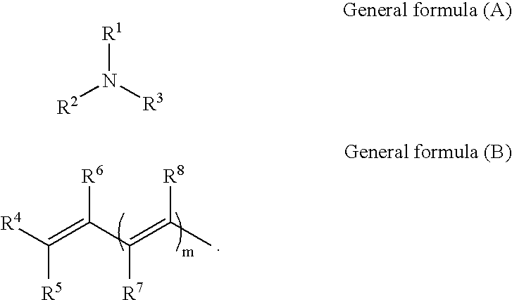
A red light emitting element material with high color purity and a light emitting element using the red light emitting element material. A light emitting element material including a compound which is expressed by following general formula (A) and a light emitting element using the compound. In the following general formula (A), at least two of R1, R2, and R3 each independently represents an aryl group or heterocyclic group, and at least one of the R1, R2, and R3 contains a group expressed by following general formula (B). In the general formula (B), R4 represents a heterocyclic group or electron attracting group, R5 represents a hydrogen atom or electron attracting group, R6, R7, and R8 each independently represents a hydrogen atom or substituent, and m represents 0, 1, or 2. However, in a case in which only one group expressed by the general formula (B) is contained in the general formula (A), R4 and R5 are not cyano groups at the same time. When R5 is a hydrogen atom, R4 represents a heterocyclic group which has aromatic rings and is formed from 3 to 7 rings

Description

[0001]This is a divisional of Application No. 09 / 540,905, filed Mar. 31, 2000, now U.S. Pat. No. 6,537,687; the disclosure of which is incorporated herein by reference.BACKGROUND OF THE INVENTION[0002]1. Field of the Invention[0003]The present invention relates to a light emitting element material, amine compound, and organic light emitting element using the light emitting element material and amine compound, which are used for a flat surface light source and display, and more specifically, to a light emitting element material, amine compound, and light emitting element using the light emitting element material and amine compound which, with application of low voltage, can emit light ranging from green to red with high luminance and high efficiency.[0004]2. Description of the Related Art[0005]An organic light emitting element in which an organic material is used (hereinafter, referred to upon occasion there is a case in which it is referred as “an organic EL element”) is promising f...

Claims


Application Information

Patent Timeline
Patent Type & Authority Patents(United States)
IPC IPC(8): C09K11/06H01L51/05H01L51/30H01L51/00
CPCC09K11/06H01L51/0043H01L51/0052H01L51/0059H01L51/006H01L51/0061H01L51/0068H01L51/0069H01L51/0072H01L51/004Y10S428/917H01L51/0042H01L51/0054H01L51/0058H01L51/0067H01L51/007H01L51/0071H01L51/0081H01L2251/308H10K85/146H10K85/141H10K85/151H10K85/622H10K85/626H10K85/636H10K85/633H10K85/655H10K85/656H10K85/6565H10K85/615H10K85/631H10K85/654H10K85/657H10K85/324H10K85/6572H10K2102/103
Inventor NII, KAZUMI
Owner FUJIFILM CORP
Why Eureka
Try Eureka