
Ultrasound transmit pulser with receive interconnection and method of use

a technology of ultrasound and transmit pulses, applied in the direction of mechanical vibration separation, instruments, and using reradiation, can solve the problems of insufficient real-time association imaging, high cost of two-dimensional arrays, and sparse arrays

Inactive Publication Date: 2005-05-10
SIEMENS MEDICAL SOLUTIONS USA INC
View PDF25 Cites 56 Cited by
  • Summary
  • Abstract
  • Description
  • Claims
  • Application Information

AI Technical Summary

Problems solved by technology

However, the associated imaging is not provided in real time and typically requires ECG gating.
Sparse arrays provide poor contrast resolution.
Fully sampled two-dimensional arrays use expensive additional beamforming hardware.
Furthermore, analog delays used for beamforming in the probe are expensive and large, and the beamformer in the probe may have limited programmability.
These high voltage devices are not easily integrated with the beamforming circuitry, so require additional space.
Receive circuitry designed for use with conventional data may improperly introduce noise or errors in time division multiplexed data.

Method used


Image

  • Ultrasound transmit pulser with receive interconnection and method of use
  • Ultrasound transmit pulser with receive interconnection and method of use
  • Ultrasound transmit pulser with receive interconnection and method of use

Examples


Embodiment Construction

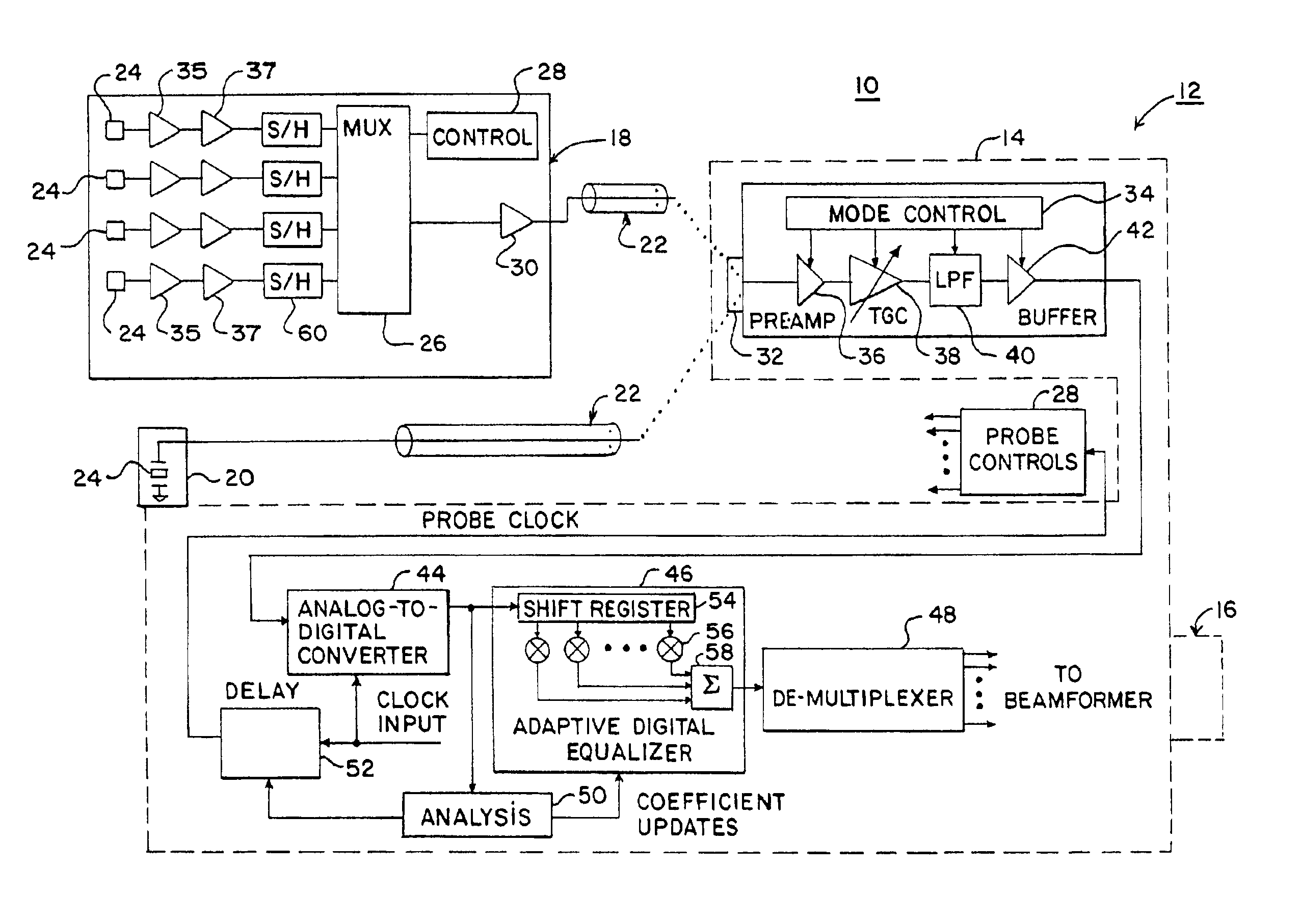
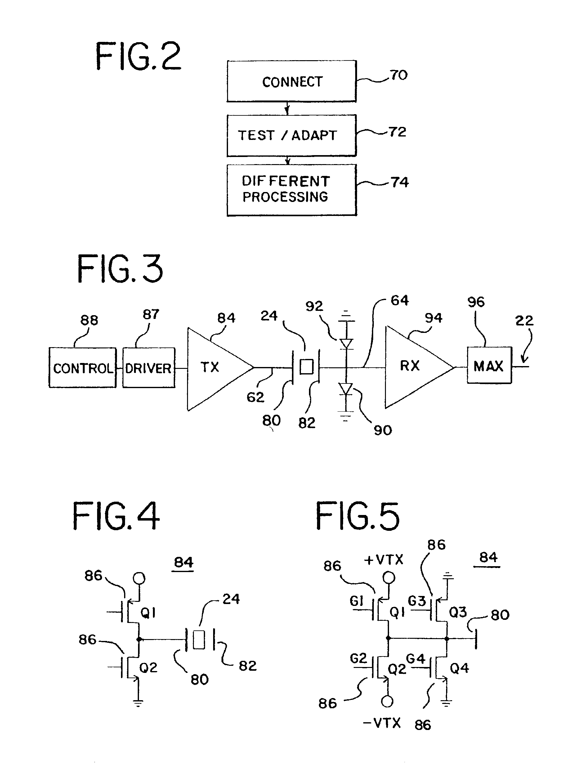
[0025]A transmit pulser with an interconnection to a receive preamplifier disclosed in FIG. 12 provides substantially symmetrical transmit waveforms. An H-bridge of transistors connects with a transducer element between a power source and a differential receive preamplifier. Diode clamps connect with inputs to the differential receive preamplifier. By using matched transistor pairs, symmetrical transmit waveforms are generated. The transmit pulser may be implemented in an application specific integrated circuit within a probe. By implementing the transmit pulser in the probe, a larger number of transducer elements may be used without requiring additional cables connected between the probe housing and a base imaging unit.

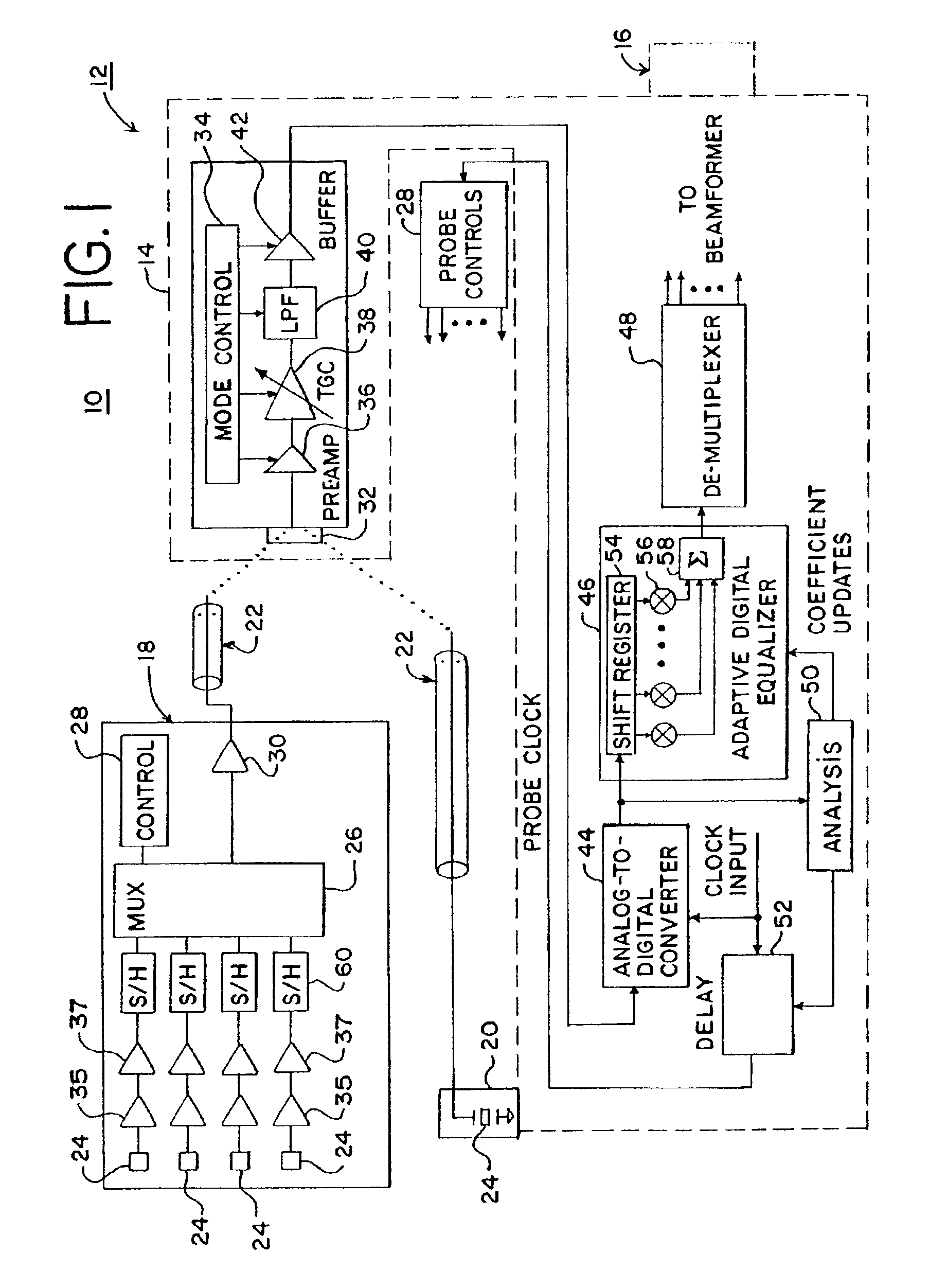
[0026]Faster or more complex two-dimensional and three-dimensional ultrasound imaging is provided by using multiplexing from a probe. A multiplexer is provided within a probe so that information from multiple transducer elements are multiplexed onto one signal channe...


PUM


Abstract

A transmit pulser includes an H-bridge of four transistors. First and second transistors of the H-bridge connect with a first electrode of a transducer element, and third and fourth transistors of the H-bridge connect with a second electrode of the transducer element. A differential receive amplifier connects with the first and third transistors. First and second diode clamps connect with the first and third transistors, respectively, and the inputs to the differential receive amplifier. The second and fourth transistors connect to a same power or voltage source, imposing a same voltage in either a forward or a reverse direction. By using matched transistor pairs (e.g. first and third matched pair and second and fourth matched pair), symmetrical transmit waveforms are generated. Symmetrical transmit waveforms allow for using phase inversion or phase differences between transmit waveforms for imaging, such as for harmonic imaging of tissue. The spectral content of symmetrical waveforms is narrower or includes less harmonic information.

Description

RELATED APPLICATIONS[0001]This application is a continuation-in-part of U.S. Pat. No. 6,806,623 (application Ser. No. 10 / 185,404), (application Ser. No. 10 / 184,461) and (application Ser. No. 10 / 184,785), all filed on Jun. 27, 2002, the disclosures of which are incorporated herein by reference.BACKGROUND[0002]The present invention relates to transmit pulsers for ultrasound imaging. In particular, transmit pulsers with interconnections to receive circuits are provided.[0003]Ultrasound imaging for echocardiography applications requires transducers with high volume-per-second rates for scanning. For real-time imaging of moving structures, 20 or more, such as 35, two or three-dimensional representations are generated each second. Large amounts of information are communicated from an ultrasound probe to an ultrasound system base unit.[0004]Various transducers and associated beamformers have been provided for three-dimensional ultrasound imaging. Currently, mostly mechanical transducers ar...

Claims


Application Information

Patent Timeline
Patent Type & Authority Patents(United States)
IPC IPC(8): B06B1/06G01S7/524G01S7/523G10K11/34G10K11/00G01S15/89G01S15/00G01S7/00G01S7/52
CPCB06B1/0622G01S7/5208A61B8/483G10K11/346G01S7/5202A61B8/56G01S7/003G01S7/5205G01S15/8961G01S15/8925
Inventor PHELPS, ROBERTPETERSEN, DAVID A.
Owner SIEMENS MEDICAL SOLUTIONS USA INC
Learn More