Magnetic heads for perpendicular recording and magnetic recording disk apparatus using the same
a technology of magnetic recording disk and perpendicular recording, which is applied in the manufacture of head surfaces, instruments, data recording, etc., can solve the problems of preventing the effective track width from decreasing, suppressing the amount of side writing, and increasing recording performance.
- Summary
- Abstract
- Description
- Claims
- Application Information
AI Technical Summary
Benefits of technology
Problems solved by technology
Method used
Image
Examples
embodiment 1
(Embodiment 1)
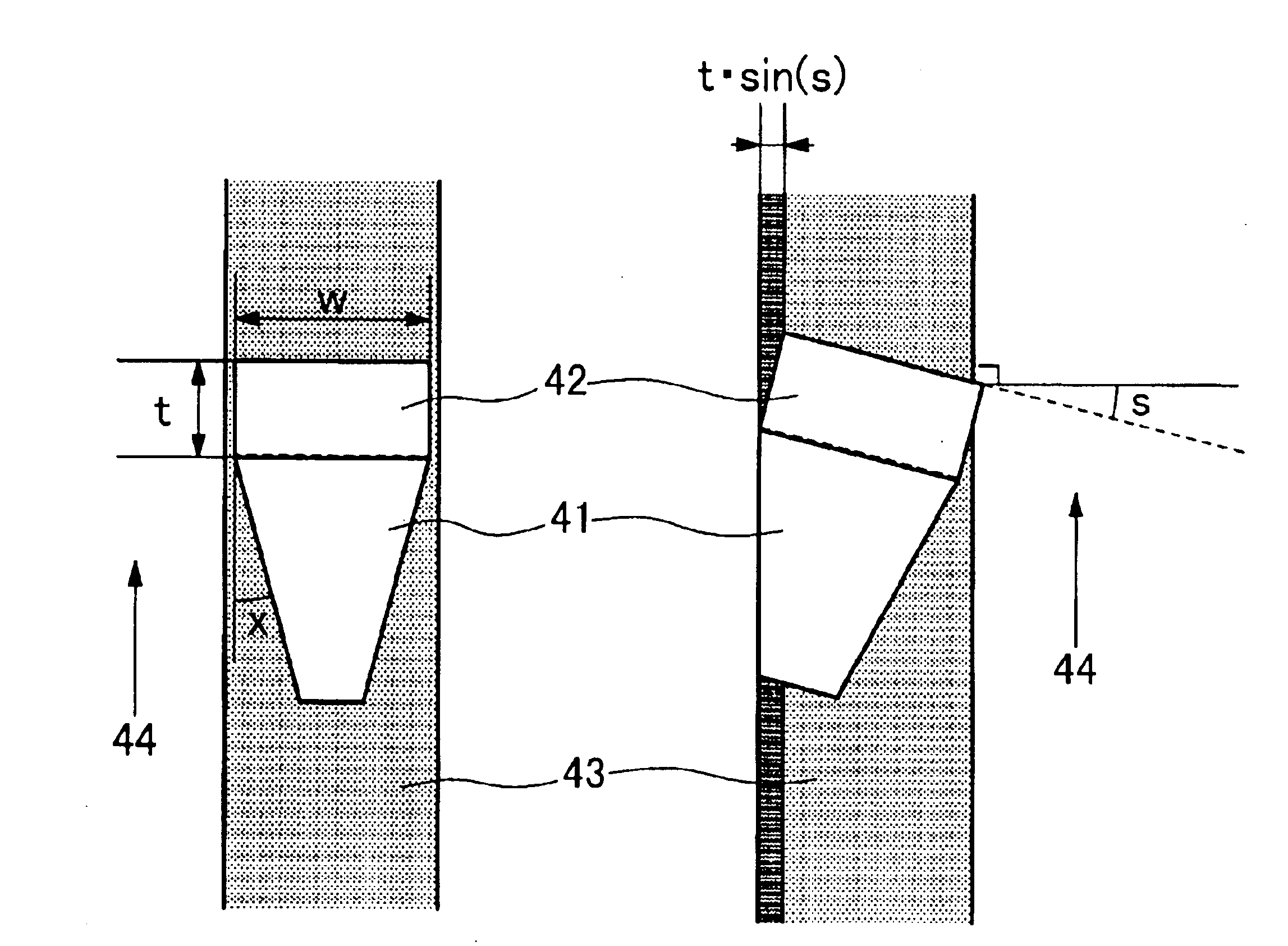
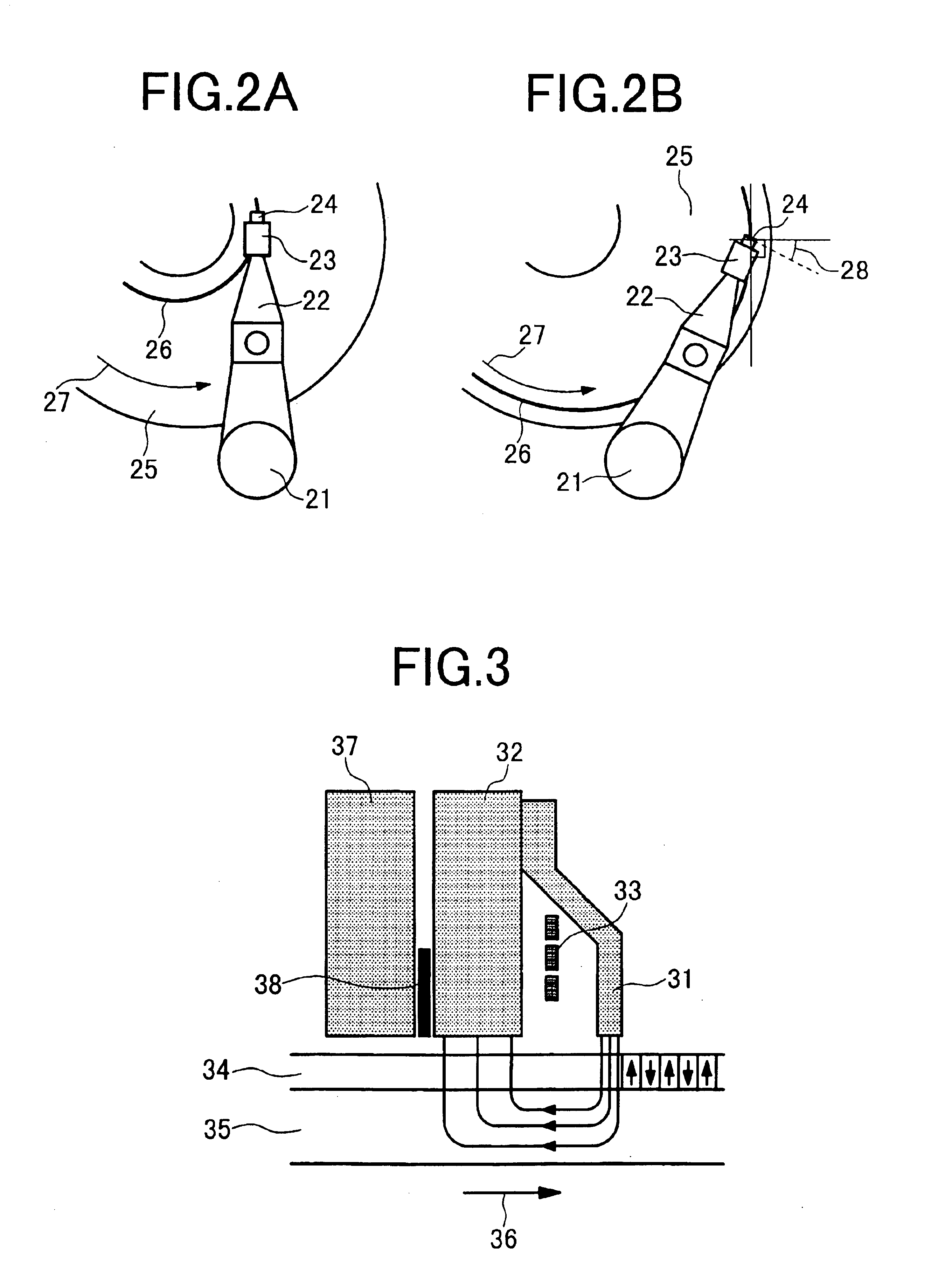
[0027]FIG. 18 is a schematic view showing a magnetic recording disk apparatus representing an embodiment of the present invention. A slider 183 is fixed at the tip of a suspension arm 182 supported by a rotary actuator 181. There is a supporting mechanism referred to as gimbals (not shown) at the tip of the suspension arm 182. The slider is fixed through the gimbals to the suspension arm. Data is written to or read from a medium 186 for perpendicular recording, which rotates in an indicated rotational direction 185, through a magnetic head element 184 provided at the tip of the slider. The recording head element 184 uses a single-pole type head for writing and a magnetoresistive effect head for reading. As the rotary actuator 181 rotates, the head element 184 is moved to a position with a different radius on the disk. In this process, a concentric recording track 187 is formed on the medium. The radius difference between one recording track and a track adjacent to it i...
embodiment 2
(Embodiment 2)
[0036]A second embodiment concerns a magnetic recording disk apparatus which is similar to the one according to the first embodiment, though it has a track pitch T of 230 nm and a maximum yaw angle s of 13 degrees. FIG. 8 schematically shows the profile of the main pole of the single-pole head used in the second embodiment on the air bearing surface. In this embodiment, the trailing edge width of a first portion 81, which continuously increases from the leading edge to the trailing edge, is 190 nm. The thickness of the first portion is 350 nm. In its second portion, which is on the side of the trailing edge of the first portion, there is a slight width increase from the leading edge to the trailing edge. More specifically, the width of the leading edge of the second portion is 190 nm and that of its trailing edge is 200 nm. Also, in this case, the change in the second portion's length in the cross-track direction from the leading edge to the trailing edge is discontinu...
embodiment 3
(Embodiment 3)
[0038]An experiment was conducted on a magnetic head which is the same as that in the first embodiment except that the Bs1 for the first portion film is 2.0T and the Bs2 for the second portion film is 1.6T. FIG. 11 shows a magnetic field strength distribution on a line along the track center at a distance of 30 nm from the head surface, as a result of estimation by computer simulation. For comparison, a similar calculation was made on a magnetic head in which the Bs for the first portion and the second portion is 1.6T. It is obvious from the graph that the magnetic field for the head with 2.0T as Bs for the first portion film is approx. 15% stronger than the other head. This means that it is possible to adequately write data even on a recording medium with a large coercive force. It has been demonstrated that when overwriting at a recording density of 700 kFCl is performed on a record made on a medium with a coercive force of 4.7 k Oe at a recording density of 88 kFCl ...
PUM
| Property | Measurement | Unit |
|---|---|---|
| yaw angle | aaaaa | aaaaa |
| thickness | aaaaa | aaaaa |
| thickness | aaaaa | aaaaa |
Abstract
Description
Claims
Application Information
 - R&D
- Intellectual Property
- Life Sciences
- Materials
- Tech Scout
- Unparalleled Data Quality
- Higher Quality Content
- 60% Fewer Hallucinations
Browse by: Latest US Patents, China's latest patents, Technical Efficacy Thesaurus, Application Domain, Technology Topic, Popular Technical Reports.
© 2025 PatSnap. All rights reserved.Legal|Privacy policy|Modern Slavery Act Transparency Statement|Sitemap|About US| Contact US: help@patsnap.com


