Acceleration sensor

a sensor and acceleration technology, applied in the field of acceleration sensors, can solve the problems of excessive amplitude of the mass portion, breakage of the elastic support arms, and elastic support arms may be broken when subjected to such a large impact, and achieve the effect of improving the sensitivity to acceleration

Inactive Publication Date: 2005-05-17
HITACHI METALS LTD
View PDF7 Cites 34 Cited by
  • Summary
  • Abstract
  • Description
  • Claims
  • Application Information

AI Technical Summary

Benefits of technology

[0010]An object of the invention, therefore, is to provide an acceleration sensor having a structure in which elastic support arms are not broken even if ...

Problems solved by technology

The acceleration sensor that can detect a small acceleration has led to an excessive amplitude of the mass portion, when subjected to a large impact, and resulted to break the elastic support arms.
Although such an excessive amplitude of the mass portion caused by a large acceleration can be prevented by the regulation plates mounted over/below the a...

Method used


Image

  • Acceleration sensor
  • Acceleration sensor
  • Acceleration sensor

Examples


example 1

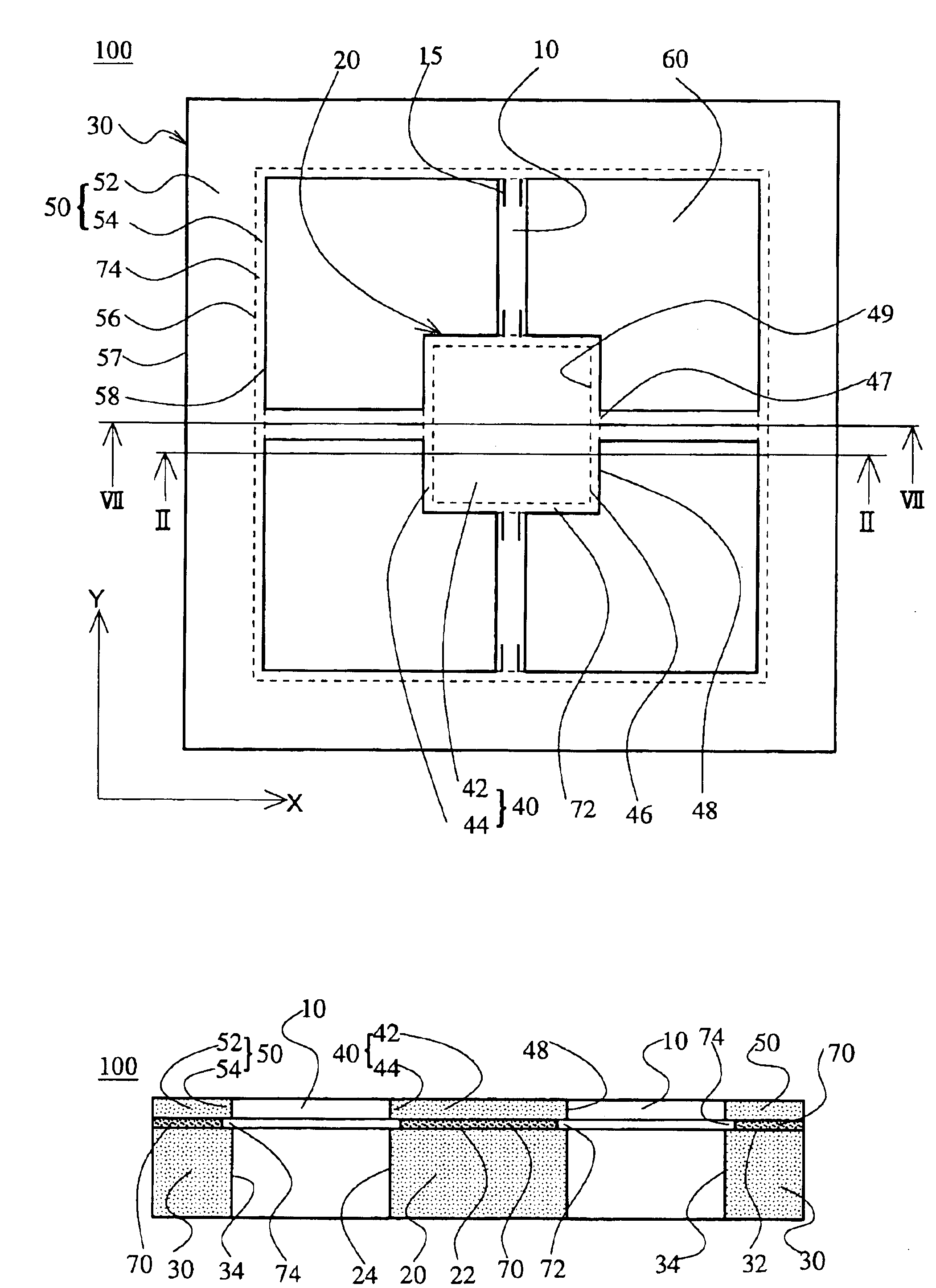
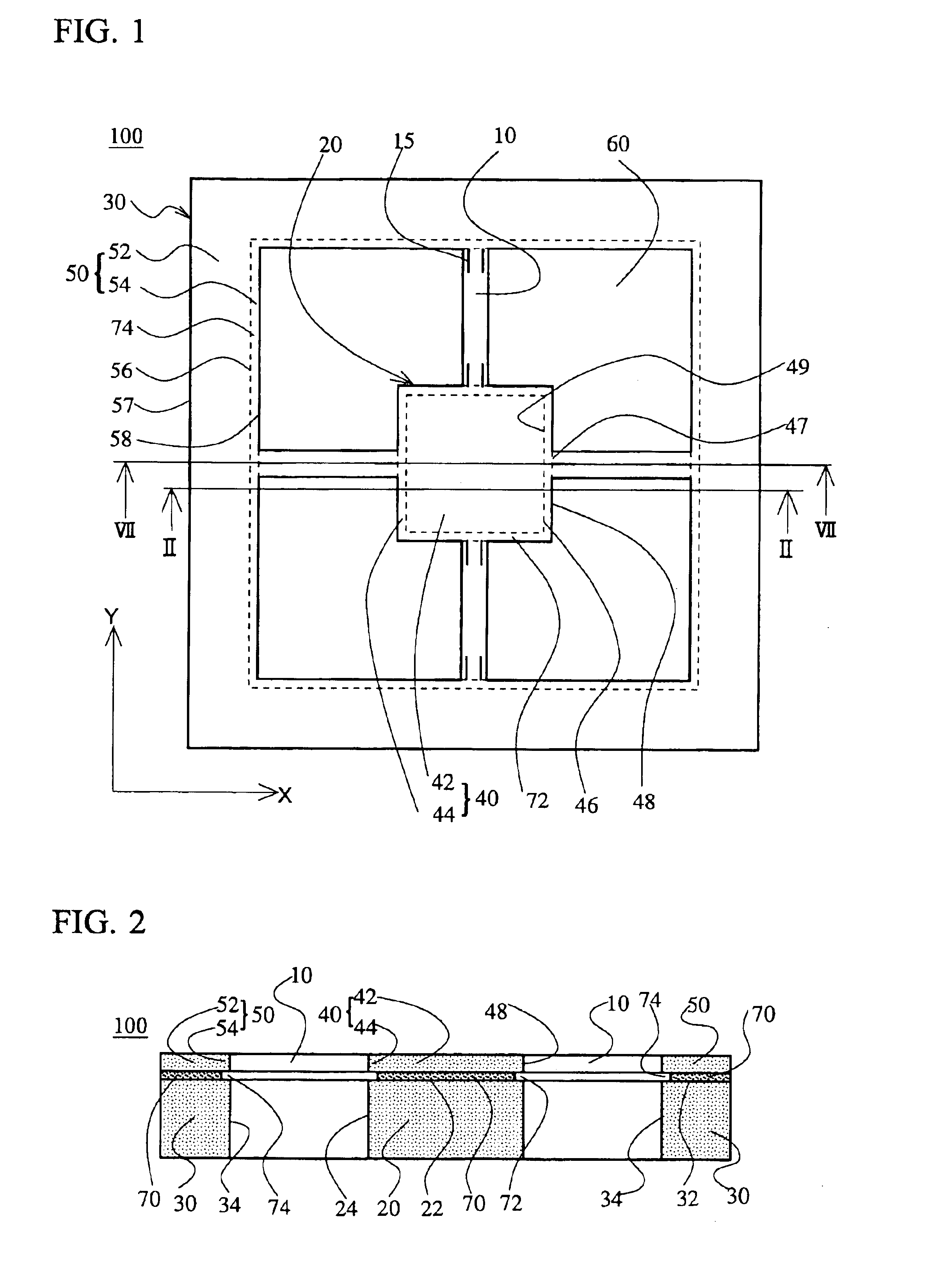
[0063]The first embodiment of the invention will be explained, referring to FIGS. 1 through 6. FIG. 1 is a plan view of a semiconductor acceleration sensor element 100 of the first embodiment, FIG. 2 is a cross sectional view taken along the line II—II of FIG. 1, FIG. 3 is a perspective view of the acceleration sensor element shown in FIG. 1, FIG. 4 is an upended perspective view of the acceleration sensor element of FIG. 3, FIG. 5 is an enlarged perspective view of part of FIG. 3, and FIG. 6 is an enlarged cross sectional plan view taken along the line VI—VI of FIG. 5.

[0064]The acceleration sensor element 100 for the present invention uses a silicon single crystal substrate with an SOI layer being formed via a SiO2 insulation layer, namely, an SOI wafer, in order to make it possible to control the thickness of elastic support arms with high precision. The SOI is an abbreviation of Silicon On Insulator. In this example, a wafer formed by thinly forming the SiO2 insulation layer bein...

example 2

[0086]Referring to FIGS. 8 through 12, an acceleration sensor element of the second embodiment according to the invention will be explained below. FIG. 8 is a plan view of the acceleration sensor element of the second embodiment, FIG. 9 is a cross sectional view taken along the line IX—IX of FIG. 9, FIG. 10 is an enlarged explanatory perspective view of part of the acceleration sensor element, FIG. 11 is an enlarged cross sectional plan view taken along the line XI—XI of FIG. 10 and FIG. 12 is an exploded perspective view of the acceleration sensor element of the second embodiment. In these drawings and the description below about the acceleration sensor element of the second embodiment, like reference numerals are used to refer to like parts.

[0087]Although the acceleration sensor element 200 of the second embodiment is almost the same as the acceleration sensor element 100 of the first embodiment, the sensor element 200 does not have an SiO2 insulating layers the first embodiment h...

example 3

[0091]Referring to FIG. 13, an acceleration sensor 300 of the third embodiment assembled with the semiconductor acceleration sensor element 100 of the first embodiment will be explained. FIG. 13 is a cross sectional view of the acceleration sensor.

[0092]In the cross sectional view shown in FIG. 13, a first regulation plate 310 made of borosilicate glass of 0.3 mm thick is fixed with paste 320 on each corner of the top surface of the thick support frame top plate 50 to cover the acceleration sensor element 100 explained in the first embodiment. The paste is silicon-rubber resin adhesive, such as DA 6501 from Dow Corning Toray Silicone Co., Ltd., mixed with about 10 mass % of hard plastic balls made of divinylbenzene-based cross-linked copolymer having diameters of approximately 10 μm. The silicon-rubber resin adhesive is elastic enough to absorb the applied impact and shows Young's Modulus less than 8.8×10⁻⁴ G Pa after hardened. The area of the paste 320 at each of the corners of the...


PUM


Abstract

An acceleration sensor is disclosed that has a structure in which elastic support arms are not broken even if subjected to an impact that may be caused during a usual handling. The acceleration sensor comprises a mass portion, a mass portion top plate fixed onto the mass portion, a rectangular thick support frame surrounding the mass portion, a frame top plate fixed onto the frame, and four elastic support arms hanging the mass portion in the center of the frame and bridging the mass portion top plate and the frame top plate. There are provided lateral grooves just below the support arms on side surfaces of the mass portion and on inner side surfaces of the frame. Due to the grooves, the mass portion top plate and the frame top plate have their portions bonded to the mass portion/the frame and their portions protruding toward the support arms. Cross sections on boundaries between the bonded portions and the protruding portions are larger than those connecting the protruding portions to the support arms. Breakage of the elastic support arms is prevented, because the strain caused in the mass portion/the frame by an impact applied from outside is not directly transmitted to the support arms and is released in the protruding portions having a larger cross section than the support arms.

Description

BACKGROUND OF THE INVENTION[0001]1. Field of the Invention[0002]The present invention relates to an acceleration sensor for detecting acceleration, which is used for toys, automobiles, aircrafts, portable terminals and the like, and particularly to an acceleration sensor that can be produced using a semiconductor technology.[0003]2. Description of the Related Art[0004]Acceleration sensors utilizing a change in physical quantity such as a piezo resistance effect and a change in electrostatic capacity have been developed and commercialized. These acceleration sensors can be widely used in various fields, but recently, such small-sized acceleration sensors as can detect the acceleration in multi-axial directions at one time with high sensitivity are demanded.[0005]Since silicon single crystal becomes an ideal elastic body due to the extreme paucity of lattice defect and since a semiconductor process technology can be applied for it without large modification, much attention is paid to ...

Claims


Application Information

Patent Timeline
IPC IPC(8): B81B3/00G01P15/18G01P15/08G01P15/12G01P15/097H01L29/84
CPCB81B3/0072G01P15/18G01P15/0802G01P15/123B81B2201/0235B81B2203/0109B81B2203/051G01P2015/084G01P15/097
Inventor OHTOYO, DAIGOSAITOH, MASAKATSU
Owner HITACHI METALS LTD
Why Eureka
Try Eureka