Manifolded fluid delivery system

a fluid delivery system and fluid injection technology, applied in the field of fluid injection systems, can solve the problems of high cost of liquid injection systems, high cost of maintenance and manufacture, and bulky conduit assemblies requiring even a mere additional square feet of space,

Inactive Publication Date: 2005-05-17
PARKER INTANGIBLES LLC
View PDF25 Cites 24 Cited by
  • Summary
  • Abstract
  • Description
  • Claims
  • Application Information

AI Technical Summary

Benefits of technology

[0010]The present invention provides an integrated fluid delivery system (IFDS) for providing fluid streams to a destination. In an exemplary embodiment, the delivery system includes a first modular manifold for internally channeling the fluid streams along seamless slots. The first modular manifold receives each of the fluid streams at a corresponding porting aperture thereof. At least one fluid device from a group consisting of a flow controller, a valve, a filter and a pressure transducer is provided. The at least one fluid device is in fluidic communication with a corresponding one of the fluid streams of the first modular manifold to dispense the high purity fluid streams from the integrated liquid delivery system to a destination, such as a wafer processing chamber.

Problems solved by technology

As can be appreciated, the number of high cost conduit assembly (i.e., valving) and high integrity welding connections, as well as the increased complexity of the corresponding system schematic leads to liquid delivery systems which are costly to both maintain and manufacture.
Indeed, bulky conduit assemblies requiring even a mere additional square foot can be cost prohibitive in the valuable real estate of clean room environments, where the cost to build per square foot is especially expensive.
Moreover, repairing a faulty weld or replacing a flow device component often necessitates disassembly of a substantial portion of the liquid delivery system.
This also increases the down time of the process incorporating the component.
As can be appreciated, conduit system 7 is complex and costly to assemble and operate.
Measuring the flow volume of an entire fluid stream, however, can lead to long response time.
These flow controllers, however, employ methods for maintaining the necessary pressure differential that are expensive, have high part counts that add tolerances and cost, or are difficult to manufacture yielding inadequate accuracy or repeatability.
However, this technique creates a dead volume of material upon discontinuance of the process.
Further, bubbling can often be an unpredictable method of vaporization, in which the precise quantity of the liquid reactant is difficult to control.

Method used


Image

  • Manifolded fluid delivery system
  • Manifolded fluid delivery system
  • Manifolded fluid delivery system

Examples


Embodiment Construction

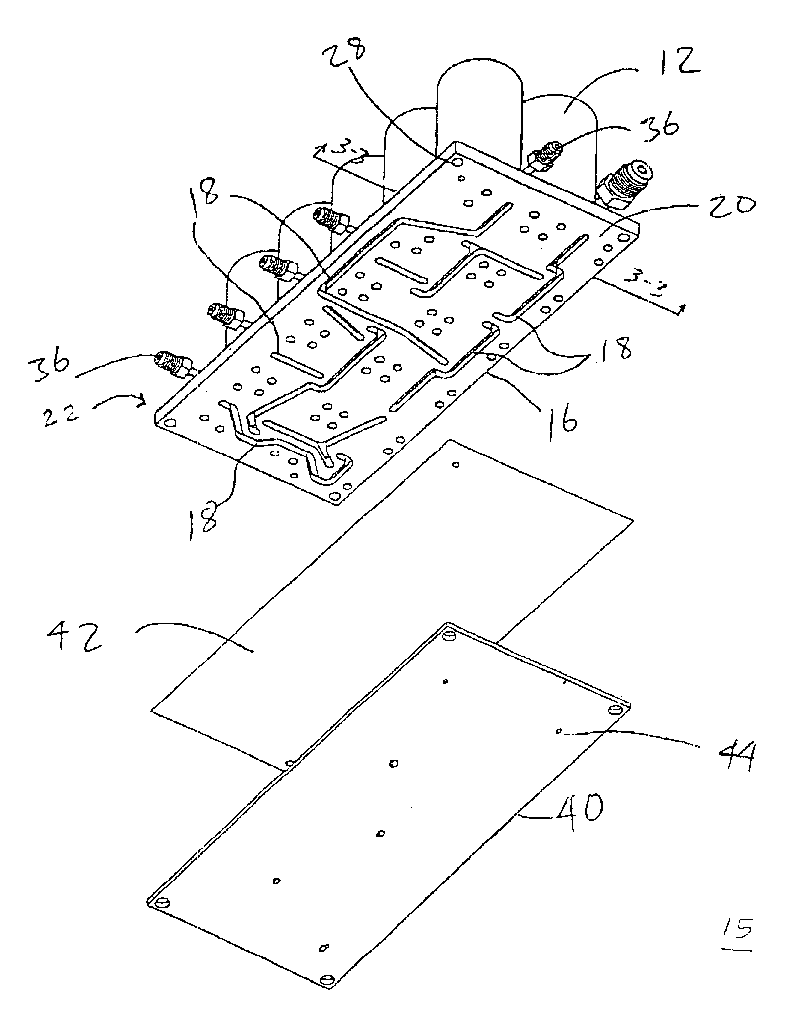
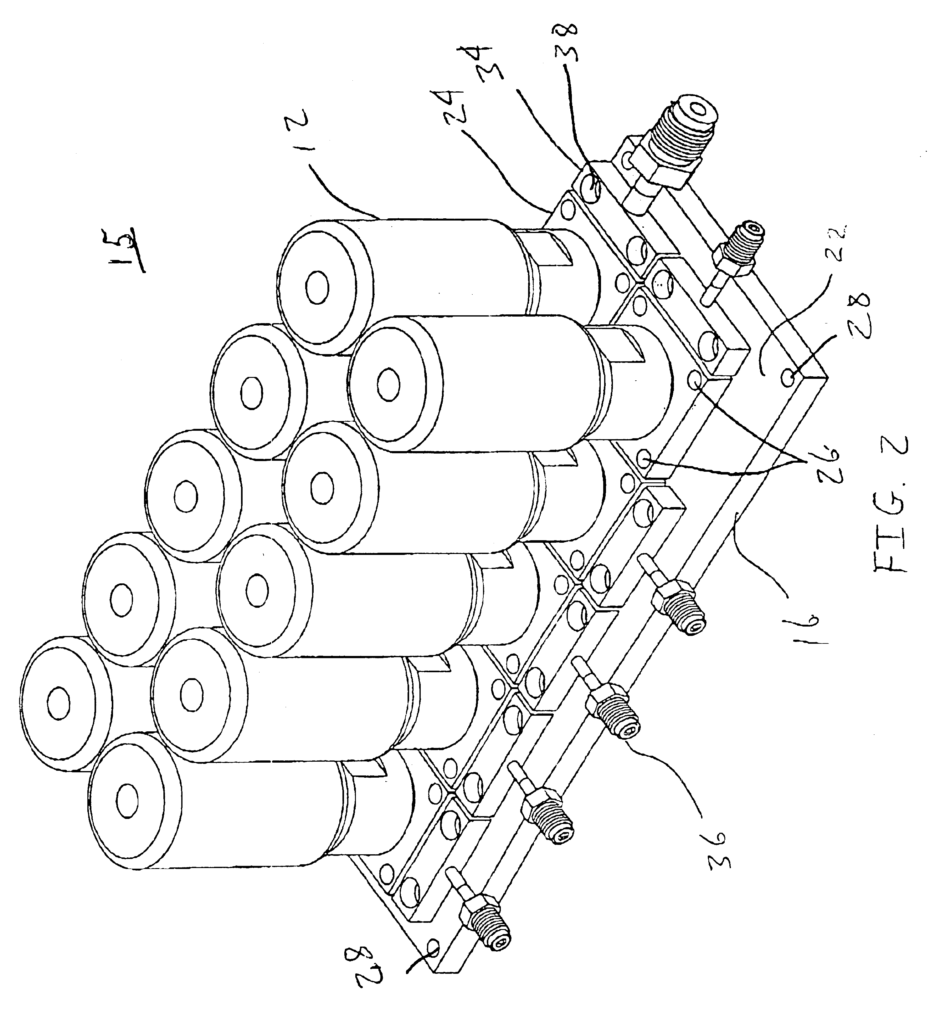
[0029]Certain terminology used in the following description is for convenience only and is not limiting. The words “right,”“left,”“ lower,” and “upper” designate directions in the drawings to which reference is made. The words “inwardly” and “outwardly” refer to directions toward and away from, respectively, the geometric center of the liquid delivery system and manifold in accordance with the present invention and designated parts thereof. The terminology includes the words noted above as well as derivatives thereof and words of similar import. The term “seamless” is generally defined as designating a continuous slot surface connecting corresponding manifold apertures.

[0030]I. Single Sided Manifold

[0031]In accordance with the present invention, an integrated fluid delivery system (IFDS) is provided to dispense fluid streams. In an exemplary embodiment, the fluid streams are of high purity. The high purity fluid streams are typically utilized to manufacture semiconductor devices and...


PUM

PropertyMeasurementUnit
temperatureaaaaaaaaaa
response timeaaaaaaaaaa

Abstract

An integrated fluid delivery system (IFDS) is provided for delivering fluid streams such as high purity fluid streams to a processing destination, such as a wafer processing chamber. The delivery system includes a first modular manifold for internally channeling the high purity fluid streams along seamless slots. The first modular manifold receives each of the high purity fluid streams at a corresponding porting aperture. At least one fluid device from a group consisting of a flow controller, a valve, a filter and a pressure transducer is provided. The at least one fluid device is in fluidic communication with a corresponding one of the high purity liquid streams of the first modular manifold to dispense the high purity fluid streams from the integrated liquid delivery system to the wafer processing chamber.

Description

CROSS-REFERENCE TO RELATED APPLICATIONS[0001]This application claims the benefit of the priority date of Provisional U.S. Patent Application Ser. No. 60 / 271,947 filed Feb. 28, 2001 for subject matter disclosed therein.FIELD OF THE INVENTION[0002]The present invention relates, in general, to a fluid delivery system. More particularly, this invention provides an integrated fluid delivery system (IFDS) for providing high purity fluid streams, such as for a wafer processing chamber.BACKGROUND OF THE INVENTION[0003]High purity fluid delivery systems are employed in demanding manufacturing environments such as the semiconductor manufacturing industry. The delivery systems are designed to precisely dispense fluids which may be hazardous in nature (i.e., corrosive, poisonous) and / or expensive. For example, in semiconductor processing / manufacturing, various stages such as low pressure chemical vapor deposition (LPCVD), oxidation, and plasma enhanced chemical vapor deposition (PECVD), require...

Claims


Application Information

Patent Timeline
Patent Type & Authority Patents(United States)
IPC IPC(8): B01F3/04B01F5/04C23C16/448F16K27/00F22B27/14F22B27/00F22B27/16B01F23/10B05B7/04B05B7/24G05D7/06H01L21/205
CPCB01F3/022B01F3/04049B01F5/0413C23C16/4486F16K27/003F22B27/14F22B27/16C23C16/4481B01F2215/0096B67D2210/0006Y10T137/87885B01F23/12B01F23/2132B01F25/312B01F2101/58
Inventor PORTER, GEORGE K.WOLF, SETH B.ALBRECHT, CHARLES W.
Owner PARKER INTANGIBLES LLC
Why Eureka
Try Eureka