Method and kit for use with standard pipe couplings to construct a de-aerator

Inactive Publication Date: 2005-05-17
SWABEY OGILVY RENAULT
View PDF25 Cites 23 Cited by
  • Summary
  • Abstract
  • Description
  • Claims
  • Application Information

AI Technical Summary

Benefits of technology

[0016]The kit in accordance with the invention is simple to construct, easily and quickly installed, simple to maintain,

Problems solved by technology

A common problem with liquid heating and cooling systems, and liquid distribution systems in general, is the accumulation of gas pockets in distribution pipes.
Accumulations of gas may cause vapor lock that inhibits the effective distribution of the heated or cooled liquid, diminishing the efficiency of the heating or cooling system.
Gas pockets may also induce noise and cause damaging cavitation in liquid distribution pumps.
The introduction of gas into liquid distribution systems is therefore usually carefully controlled, but it cannot be completely avoided.
Liquids that readily dissolve gasses at a temperature and pressure at which the liquids are injected into a system, and emit the gasses under operating temperatures and pressures in the system, are

Method used


Image

  • Method and kit for use with standard pipe couplings to construct a de-aerator
  • Method and kit for use with standard pipe couplings to construct a de-aerator
  • Method and kit for use with standard pipe couplings to construct a de-aerator

Examples


Embodiment Construction

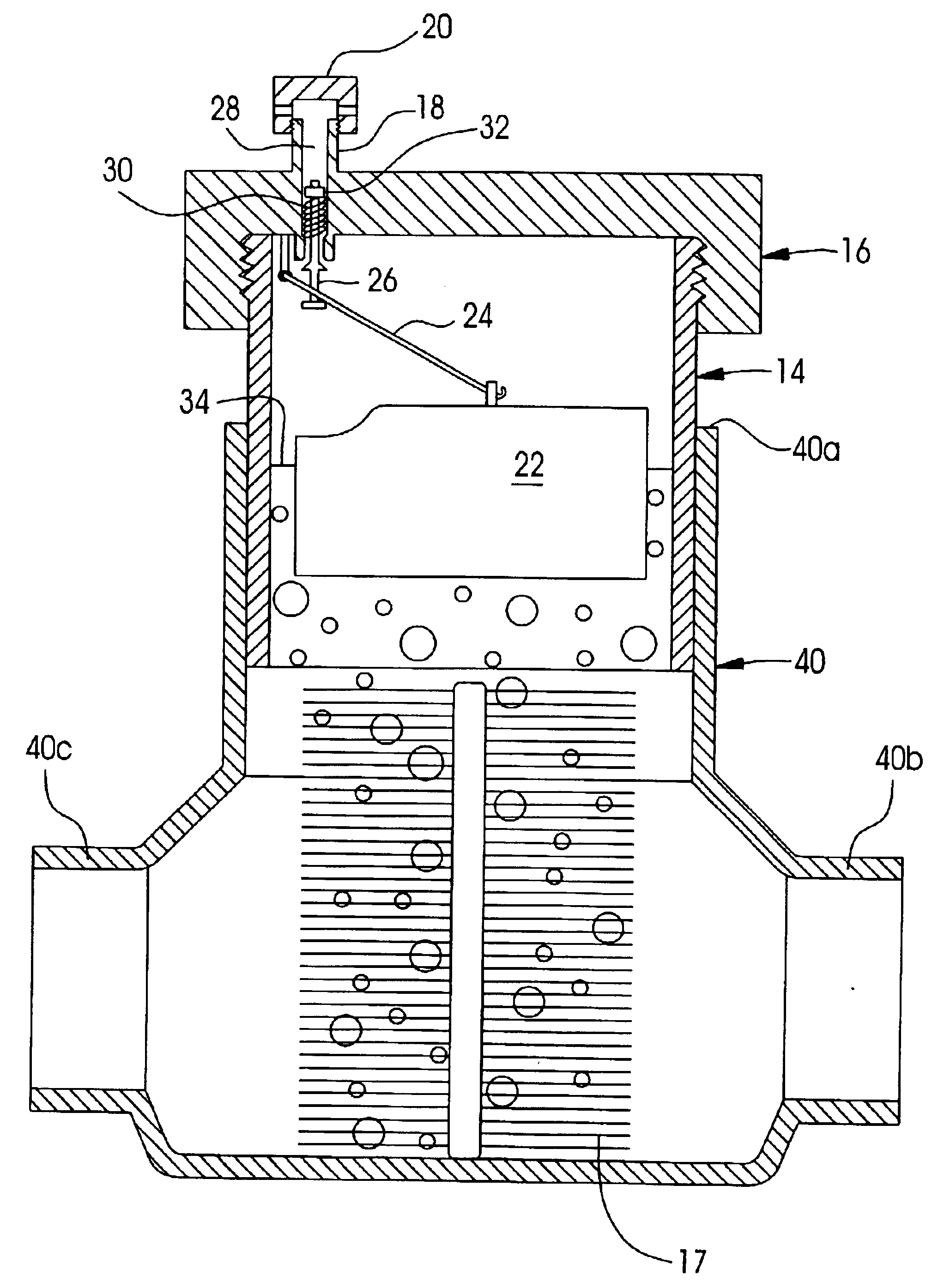
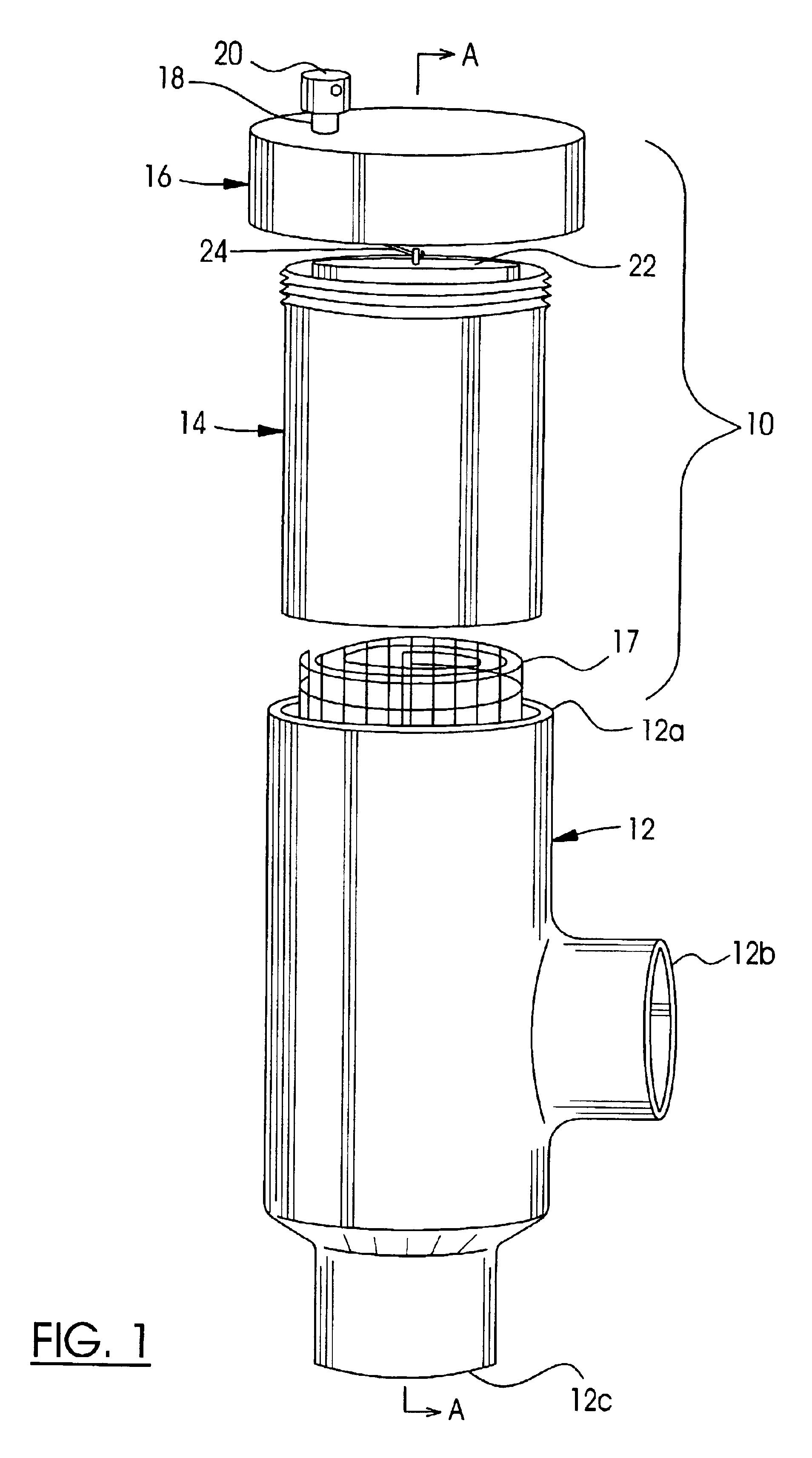
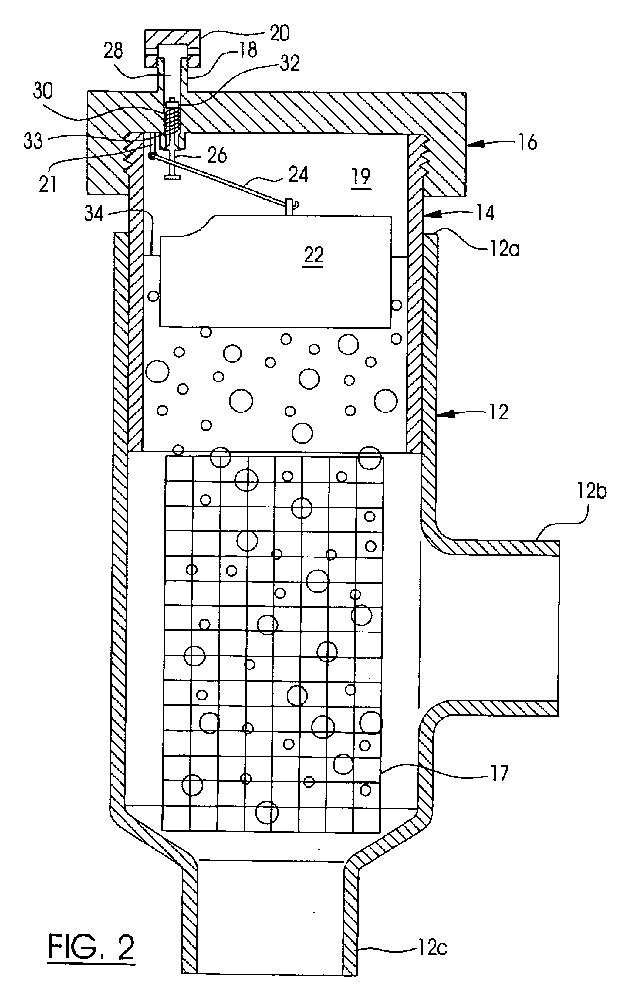
[0022]The invention provides a simple and inexpensive kit for a de-aerator that is installed in a standard T-coupling in a fluid distribution system, such as a radiant heating system, for example. The kit, generally indicated by reference 10, is installed in a standard T-coupling 12 having connectors 12a, 12b and 12c which receive standard fluid distribution pipes (not shown) that are secured to the coupling 12 by soldering, threaded joints, or the like. The kit 10 includes a fitting 14 that is extruded, cast and / or machined to a diameter of a pipe received in the connector 12a of the coupling 12. The kit further includes a cap 16 that is connected to the fitting 14 in a fluid-tight seal, and a gas concentrator 17, which in this example is a metal mesh, as will be explained below in more detail. The gas concentrator 17 is inserted directly into an unobstructed fluid flow path between an inlet, the connector 12b, for example, and an outlet, the connector 12c, for example, of the coup...


PUM

PropertyMeasurementUnit
Structureaaaaaaaaaa
Levelaaaaaaaaaa
Threshold limitaaaaaaaaaa

Abstract

A kit for constructing a de-aerator that includes a concentrator is adapted to be connected to a standard pipe coupling. The concentrator is inserted in the path of liquid conveyed through the pipe coupling for aggregating gas, and directing the gas to a cavity. The cavity is encased by the fitting which is a vertical, cylindrical sheath with one end adapted to be inserted into standard pipe couplings, and the other end adapted to be connected with the cap. The cap includes a vent adapted to open and shut in response to lowering and raising of the level of the liquid in the cavity below/above a threshold, respectively.

Description

CROSS-REFERENCE TO RELATED APPLICATIONS[0001]This is the first application filed for the present invention.MICROFICHE APPENDIX[0002]Not Applicable.TECHNICAL FIELD[0003]This invention relates to gas removal from liquid distribution systems, and, in particular, to a de-aerator for removing gas suspended in liquids used for temperature control in closed-loop heating and cooling systems.BACKGROUND OF THE INVENTION[0004]A common problem with liquid heating and cooling systems, and liquid distribution systems in general, is the accumulation of gas pockets in distribution pipes. Dissolved or suspended gases separate from the liquid and naturally collect at various points in the system. Accumulations of gas may cause vapor lock that inhibits the effective distribution of the heated or cooled liquid, diminishing the efficiency of the heating or cooling system. Gas pockets may also induce noise and cause damaging cavitation in liquid distribution pumps. The introduction of gas into liquid dis...

Claims


Application Information

Patent Timeline
IPC IPC(8): B01D19/00F16K24/04F16K24/00
CPCB01D19/00F16K24/048B01D19/0063Y10T137/3099Y10T137/3018Y10T137/309Y10T137/313
Inventor MACDUFF, JAMES
Owner SWABEY OGILVY RENAULT
Why Eureka
Try Eureka